

Deploy Tanzu in vSphere 8 with NSX and Avi Loadbalancer: #
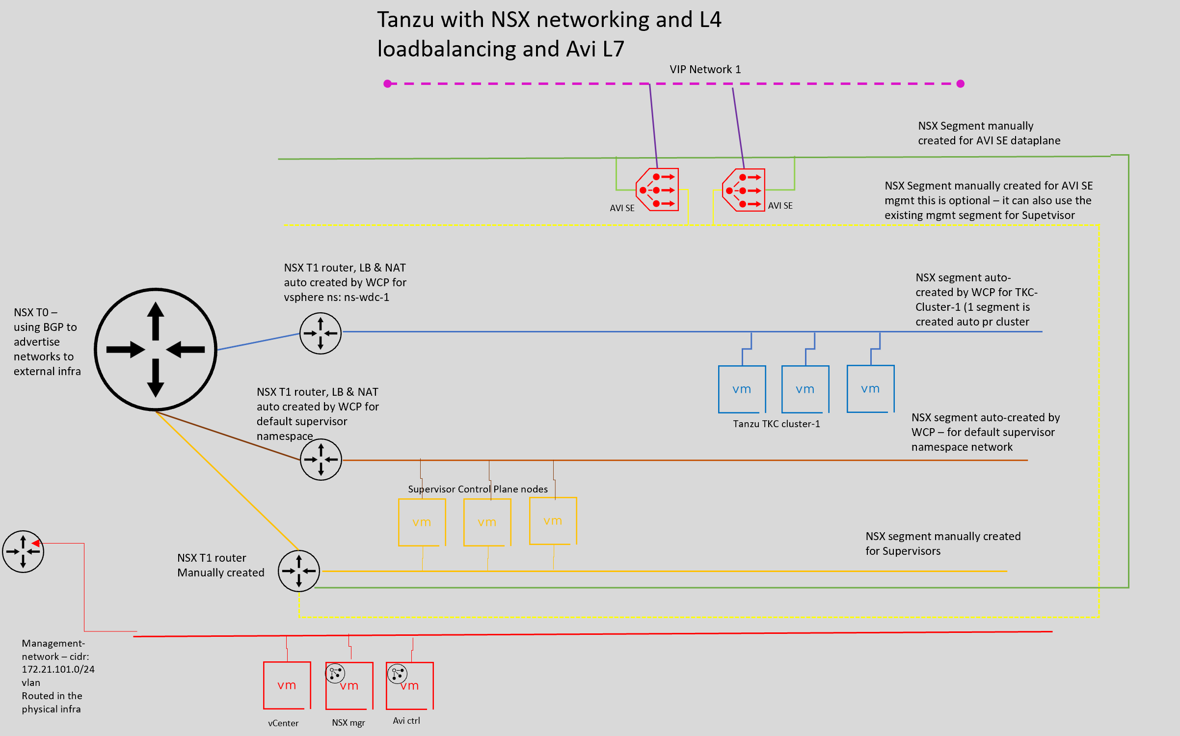
This post will go through how to install Tanzu in vSphere 8 using NSX networking (including built in L4 loadbalancer) and Avi as L7 loadbalancer. The goal is to deploy Tanzu by using NSX for all networking needs, including the Kubernetes Api endpoint (L4) and utilize Avi as loadbalancer for all L7 (Ingress). The deployment of Tanzu with NSX is an automated process, but it does not include L7 loadbalancing. This post will quickly go through how to configure NSX and Avi to support this setup and also the actual configuration/deployment steps of Tanzu. The following components will be touched upon in this post: NSX, Tanzu, TKC, AKO, NCP, vCenter, AVI and Antrea. All networks needed for this deployment will be handled by NSX, except vCenter, NSX manager and Avi controller but including the management network for the supervisor cluster and Avi SE’s. In the end we will also have a quick look at how to use Antrea Egress in one of the TKC clusters.
We should end up with the following initial network diagram for this deployment (will update it later in the post reflecting several network for our TKC cluster with and without NAT (without NAT when using Egress):
Preparations - NSX config #
This post assumes a working vSphere environment with storage configured, vMotion network, vSAN (if using vSAN), HA, DRS enabled and configured. So this step will cover the basic NSX config for this use-case. NSX will need some network configured in the physical environment like the Geneve Tunnel VLAN, Uplink VLAN(s) for our T0 in addition to the most likely already defined management network for the placement of NSX managers, NSX edges and Avi controller and/or SE’s. So lets jump in.
Initial configs in the NSX manager #
The first NSX manager is already deployed. Accept the EULA and skip the NSX tutorial:
When done, head over to System -> Licenses and add your license key. Then, still under system, head over to Appliances and add a cluster IP. Even though you only have 1 NSX manager for test/poc it can make sense to use cluster ip adding, removing nsx managers etc and still point to the same IP.
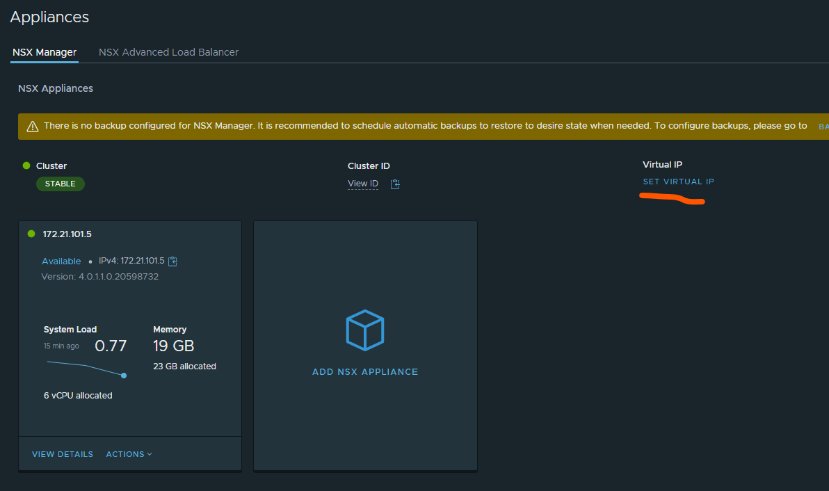
Click on Set Virtual IP and type in your wanted cluster ip. Out of the box its the same layer 2 subnet as your controllers are placed in (it possible to use L3 also but that involves an external LoadBalancer, not the built in for this purpose).
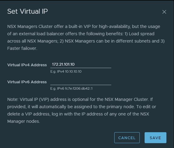
Click save and wait.
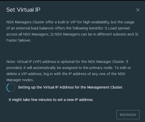
After some minutes, try to log in via your new cluster IP. All the configs I will do will be used with this IP. It does not matter if you go directly to the NSX manager itself or the cluster IP for this post.
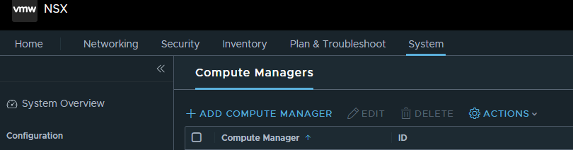
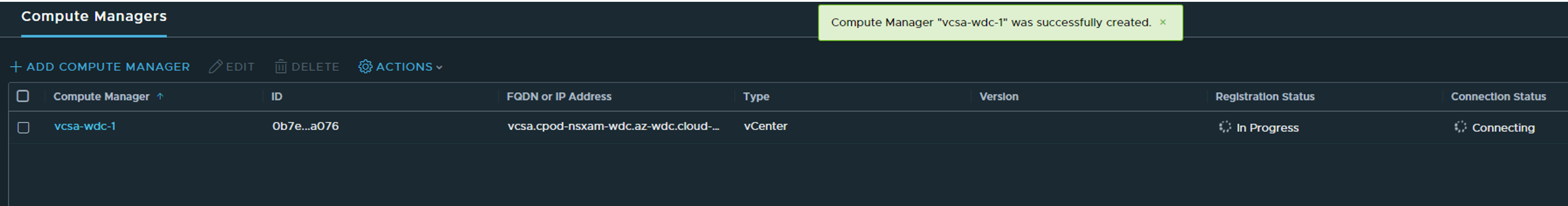
After cluster IP is done, we need to add a Compute Manager which in our case is the vCenter server (not that you have any option besides vCenter). Still under System, go to Fabric expand and find Compute Manager. From there click Add Compute Manager:
Fill in the necessary information for your vCenter and make sure Service Account and Enable Trust is enabled.
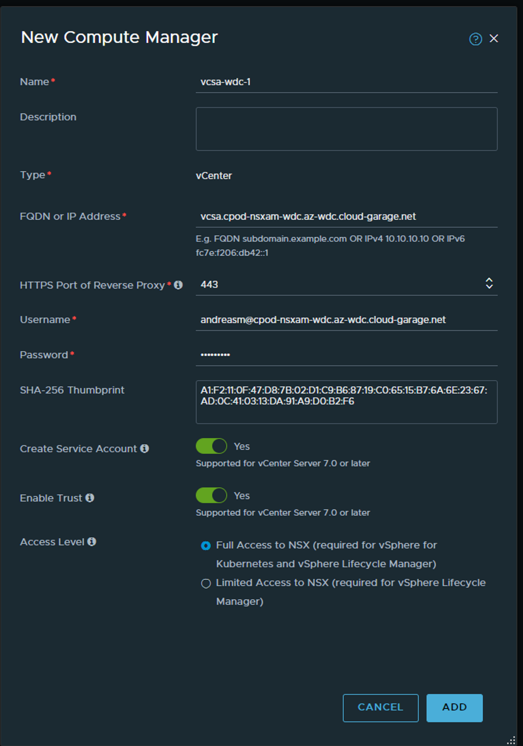
Next message will ask you to use a Thumprint the vCenter says it has. You could either just say ADD or actually go to vCenter and grab the thumbprint from there and verify or paste it in the SHA-256 field before clicking add.
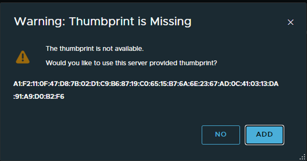
Here is how to get the thumbprint from vCenter:
root@vcsa [ ~ ]# openssl x509 -in /etc/vmware-vpx/ssl/rui.crt -fingerprint -sha256 -noout
SHA256 Fingerprint=A1:F2:11:0F:47:D8:7B:02:D1:C9:B6:87:19:C0:65:15:B7:6A:6E:23:67:AD:0C:41:03:13:DA:91:A9:D0:B2:F6
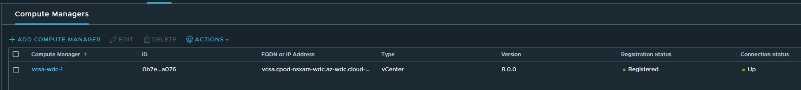
Now when you are absolutely certain, add and wait.
NSX Profiles: Uplink, Transport Zones and Transport Node Profiles #
In NSX there is a couple of profiles that needs to be configured, profiles for the Transport nodes, Edge transport nodes, transport zones. Instead of configuring things individually NSX uses profiles so we have a consistent and central place to configure multiple components from. Let start with the Uplink profiles: Under Fabric head over to Profiles.
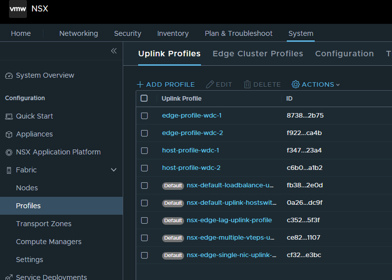
Here we need to create two uplink profiles (one for the ESXi transport nodes and one for the NSX edge transport nodes). These profile will dictate the number of uplinks used, mtu size (only for the edges after NSX 3.1) ,vlan for the geneve tunnel and nic teaming. Here we also define multiple teaming policies if we want to dictate certain uplinks to be used for deterministic traffic steering. Which I will do.
Host uplink:
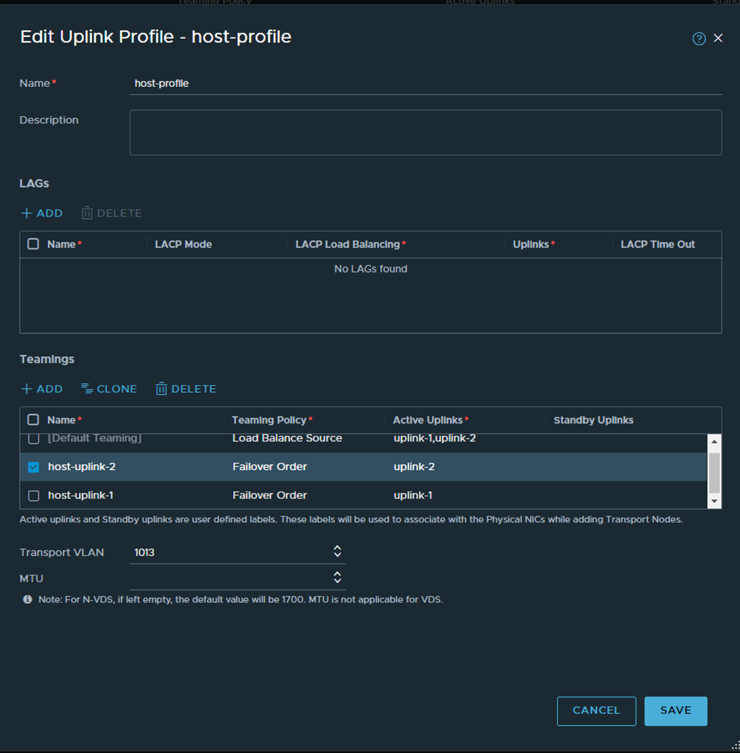
In the “host” uplink profile we define the logical uplinks, (uplink-1 and uplink-2, but we could name them Donald-Duck-1 and 2 if we wanted). We define the default teaming-policy to be Load Balance Source as we want two vmkernels for the host-tep, and default active/active if we create a vlan segment without specifying a teaming policy in the segment. Then we add two more teaming policies with Failover Order and specify one uplink pr policy. The reason for that is because we will go on and create a VLAN segment later where we will place the Edge VM uplinks, and we need to have some control over wich uplink->nic on the ESXi host the T0 Uplinks go, and we dont want to use teaming on these, and we dont want a standby uplink as BGP is supposed to handle failover for us. This way we steer T0 Uplink 1 out via uplink-1 and T0 Uplink 2 out via uplink-2 and the ESXi hosts has been configured to map uplink-1 to VDS uplink-1 which again is mapping to pNIC0 and uplink-2 to VDS uplink-2 to pNIC1 respectively. In summary we create a vlan segment on the host for the edge VM, then we create a vlan segment for the logical T0 later.
Then we define the VLAN number for the Geneve tunnel. Notice we dont specify MTU size as this will adjust after what we have in our VDS which we will map to later, so our VDS must have minumum MTU 1700 defined (it works with 1600 also, but in NSX-T 3.2 and later there is a greenfield min MTU of 1700). We will use the same VLAN for both host and edge tep wich was supported from NSX-T 3.1 and forward. But to make that work we cant use VDS portgroups for the T0, it needs to be a NSX VLAN segment. More on that later.
Click save.
Next up is the “Edge” Uplink Profile, almost same procedure:
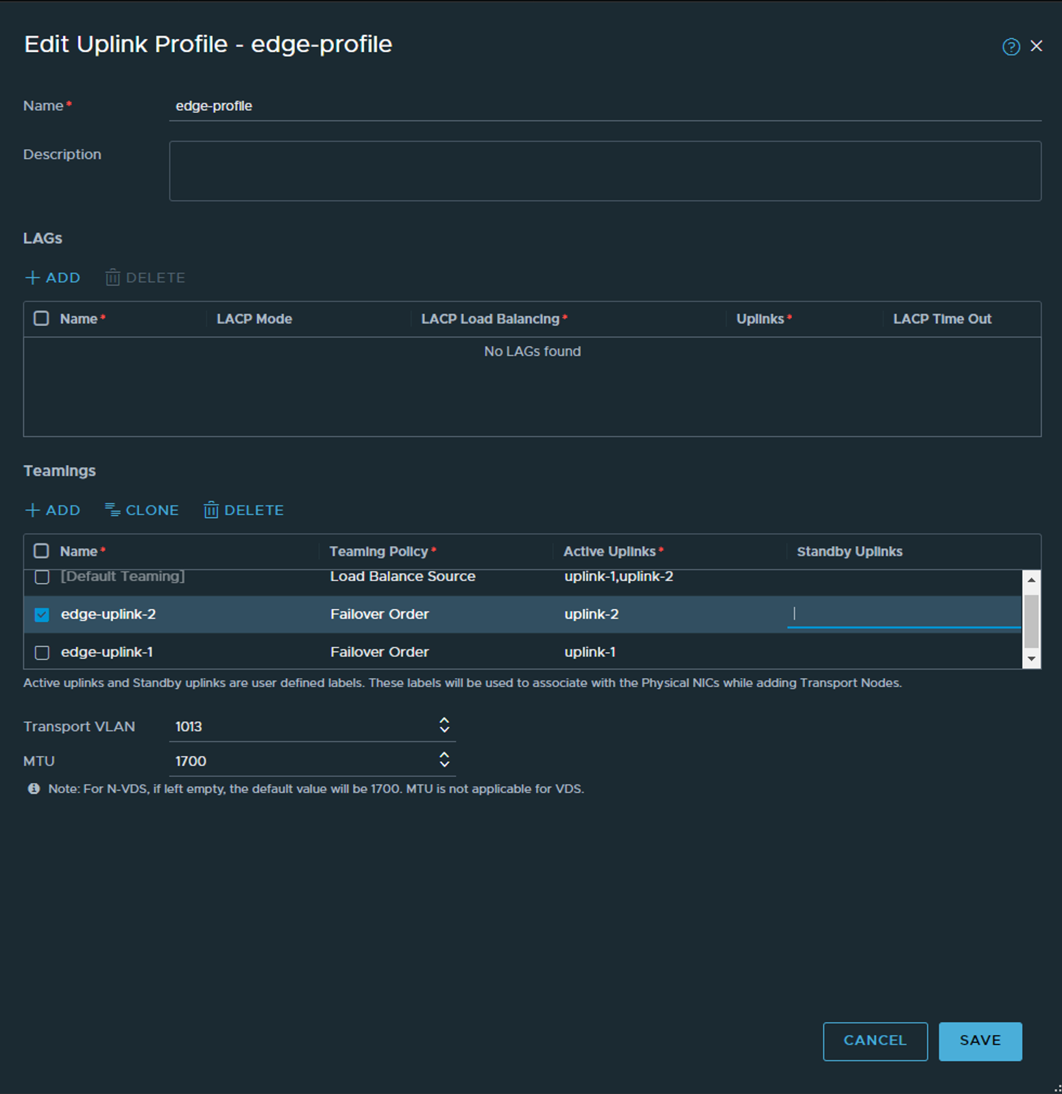
The biggest difference is the name of the specific teaming policies, and we specify a MTU size of 1700 as this is what I use in my VDS.
Now over to Transport Zones
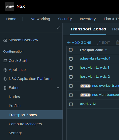
Here we create three Transport Zones: 1 vlan TZ for host, 1 vlan TZ for edge and 1 overlay which is common for both Edge and Host transport nodes.
Create host-vlan-tz:
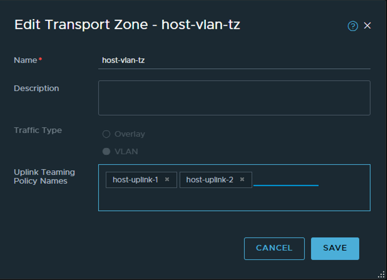
Its probably not so obvious in the GUI, but we also define our teaming policies defined in our respective uplinks earlier. Here I enter manually the uplink policy names for my host transport zone so they can be available later when I create a VLAN segment for my T0 uplinks (on the host). Click save.
When done its the edge-vlan-tz:
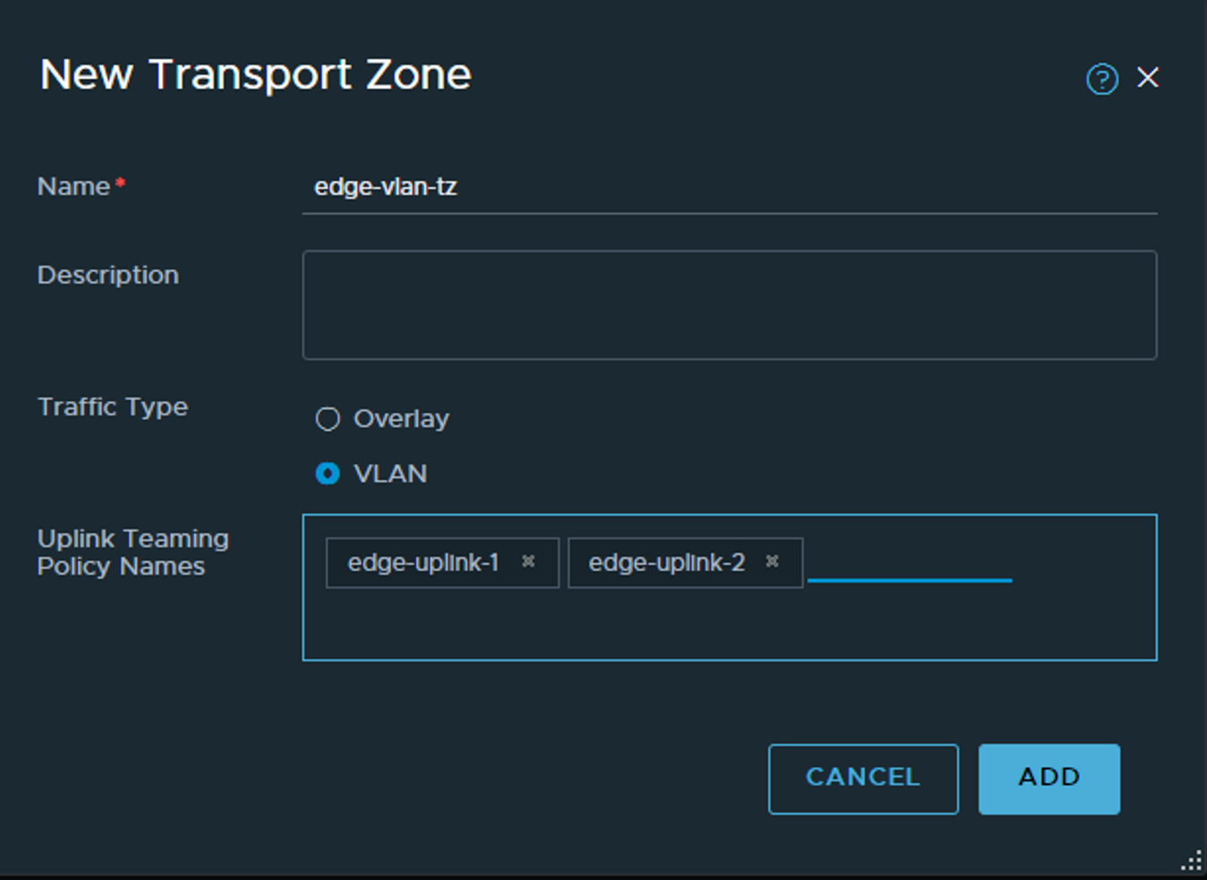
Common for both Transport Zones is VLAN.
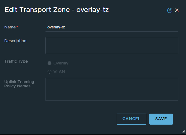
Now the last Transport Zone for now - the Overlay TZ (this one is easy):
The next step would be to create the Transport Node Profile, but first we need to create an IP-Pool for the TEP addresses. Head over to Networking and IP Address Pools :
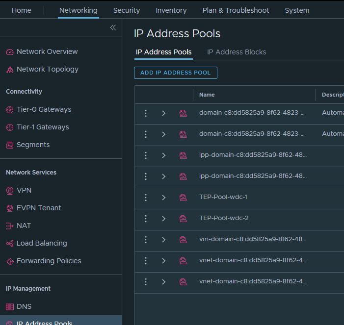
Add IP address pool:
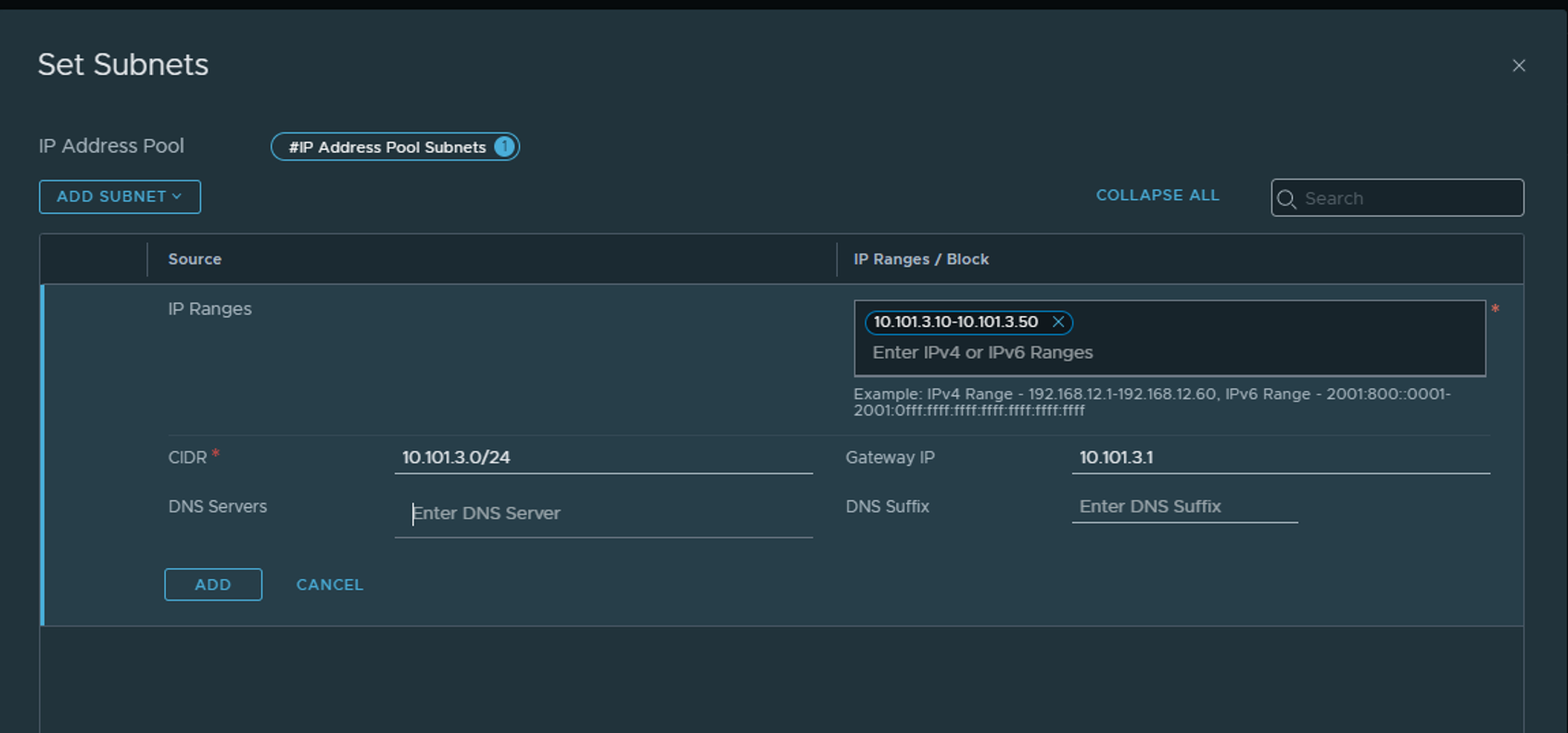
Its only necessary to define the CIDR, IP Range and Gateway IP. Please make sure the range is sufficient to support the max amount of ESXi Transport nodes and Edge nodes you will have. 2 IPs pr device.
Now back to System -> Fabric again and create the Transport Node Profile under Profile:
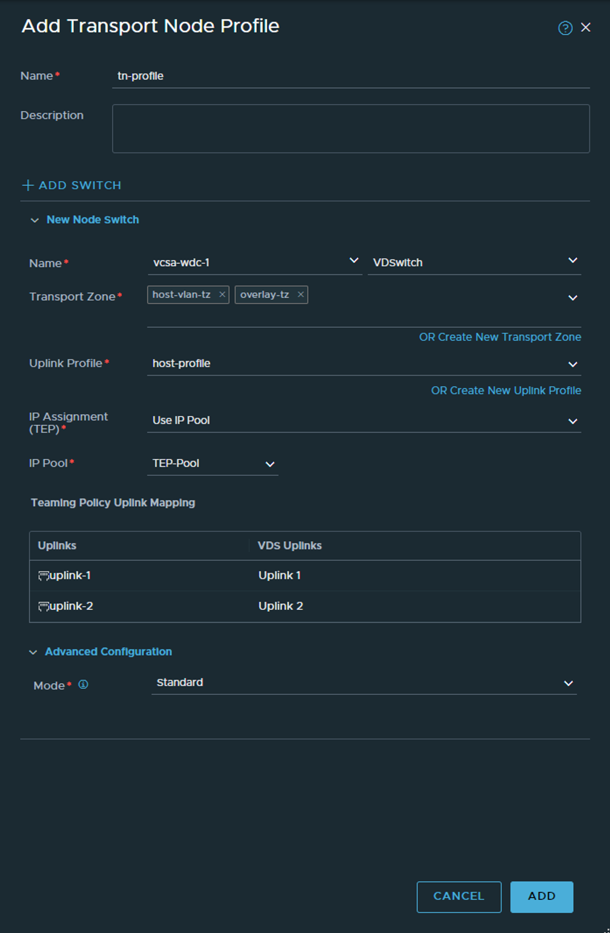
Here we select the vCenter we added earlier, point to the correct VDS we want to use, select the host-profile we created and under IP assignment we use our newly created IP pool and map the uplinks to the corresponding VDS uplinks. Then ADD
Install NSX components on the ESXi hosts #
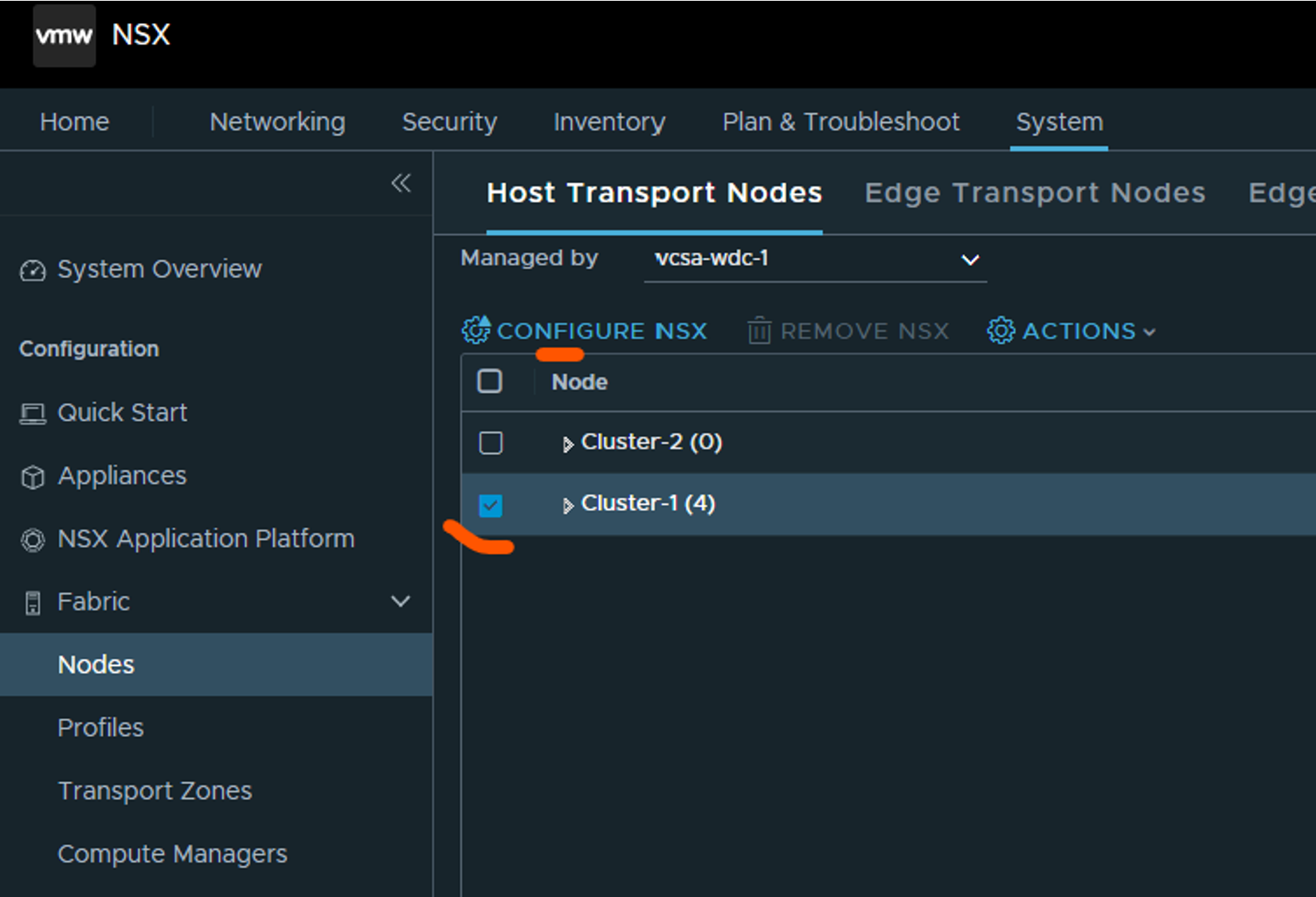
To enable NSX after our initial configs has been done is fairly straight-forward. Head over to Nodes under System->Fabric and select the first tab Host Transport Nodes. Select your vCenter under Managed by and select your cluster and click Configure NSX:
Select your (only?) transport-node profile your created above:
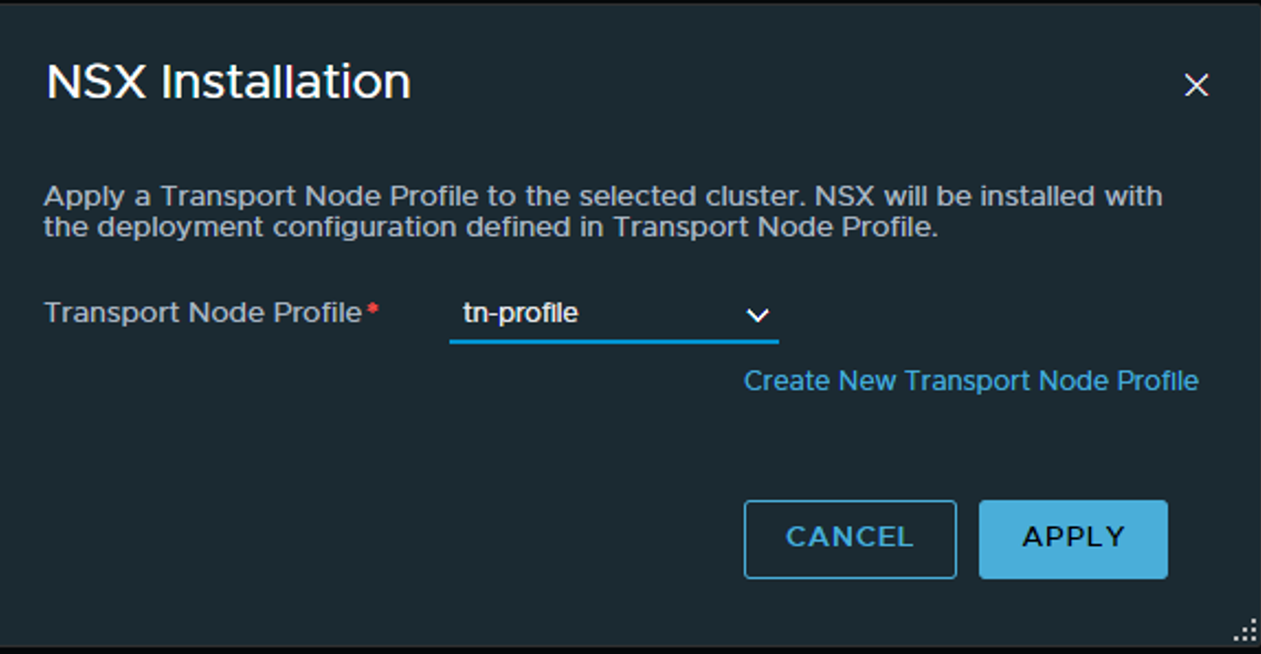
Click apply and wait…
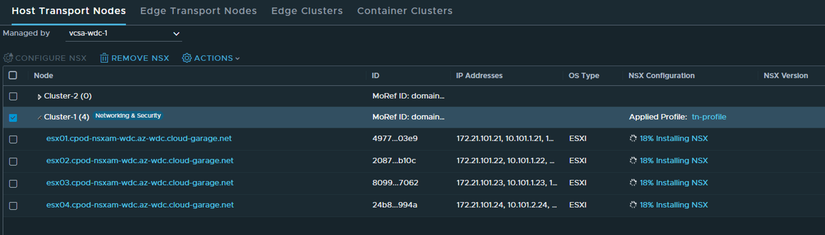
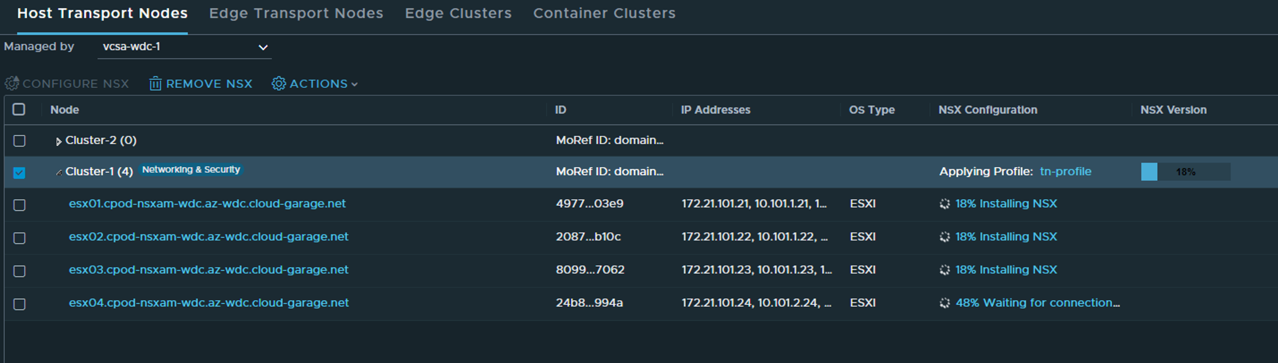
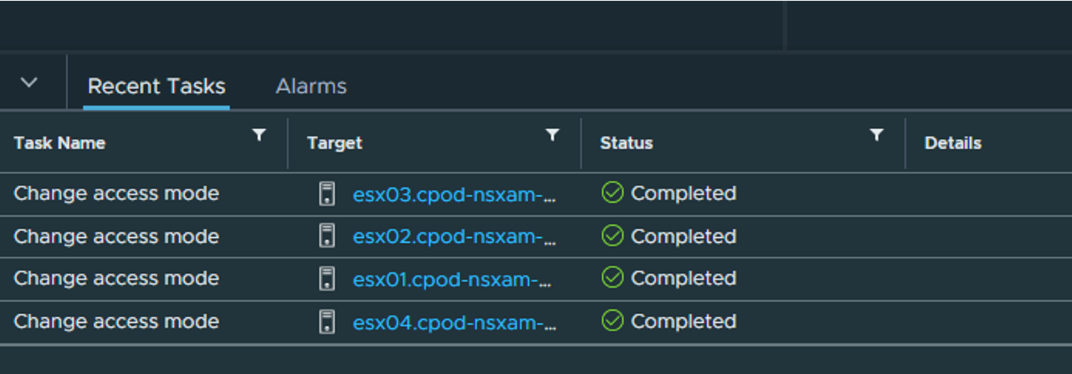
Status in vCenter - the only status we will see.
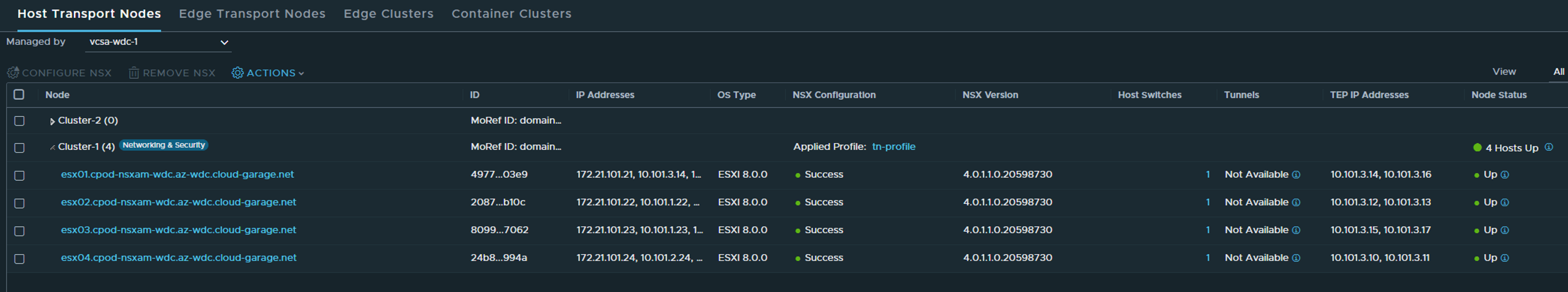
When everything is up and green as below, NSX is installed in our ESXi hosts and we are ready to create networks 😄
Deploy NSX Edges #
Deploying a Edge is quite straight forward, and is done from the NSX manager under System ->Fabric ->Nodes ->Edge Transport Nodes
But I need to create two VLAN segments for Edge “data-path/uplink interfaces. As I want to use the same VLAN for both Host Tep and Edge TEP I need to do that. These two segments will only be used for the actual Edge VMs, not the T0 I am going to create later. In my lab I am using VLAN 1013 for TEP and VLAN 1014 and 1015 for T0 Uplink 1 and 2. So that means the first VLAN segment I create will have the VLAN Trunk range 1013-1014 and the second VLAN segment will use VLAN trunk 1013,1015 Head over to the Networking section/Segments in the NSX UI click Add Segment:
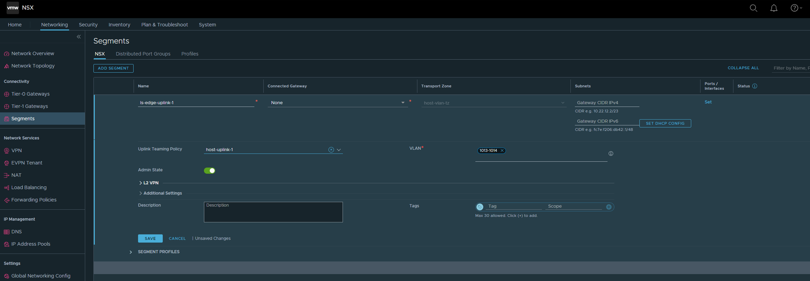
Select host-uplink-1 under Uplink Teaming Policy and add your VLAN ID under VLAN. Click save
Same procedure again for the second segment:
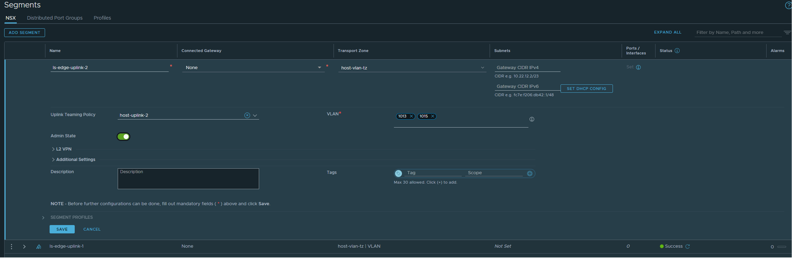
select host-uplink-2 and the correct vlan trunk accordingly.
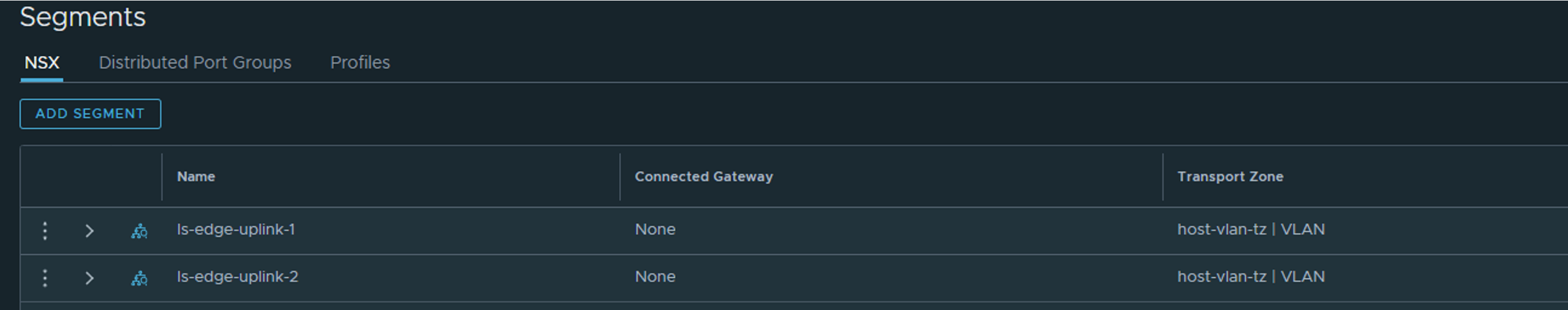
The result should be two VLAN segments, created in our host-vlan-tz (the host vlan transport zone created earlier)
Now we can deploy our Edge(s).
Head over to System ->Fabric ->Nodes ->Edge Transport Nodes
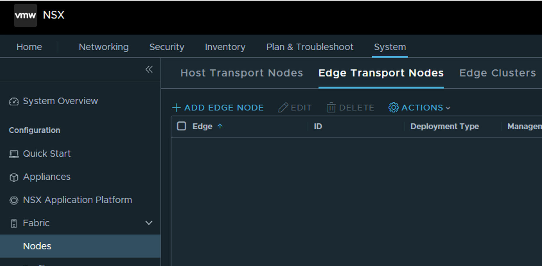
Click add edge node and start the edge deployment wizard:
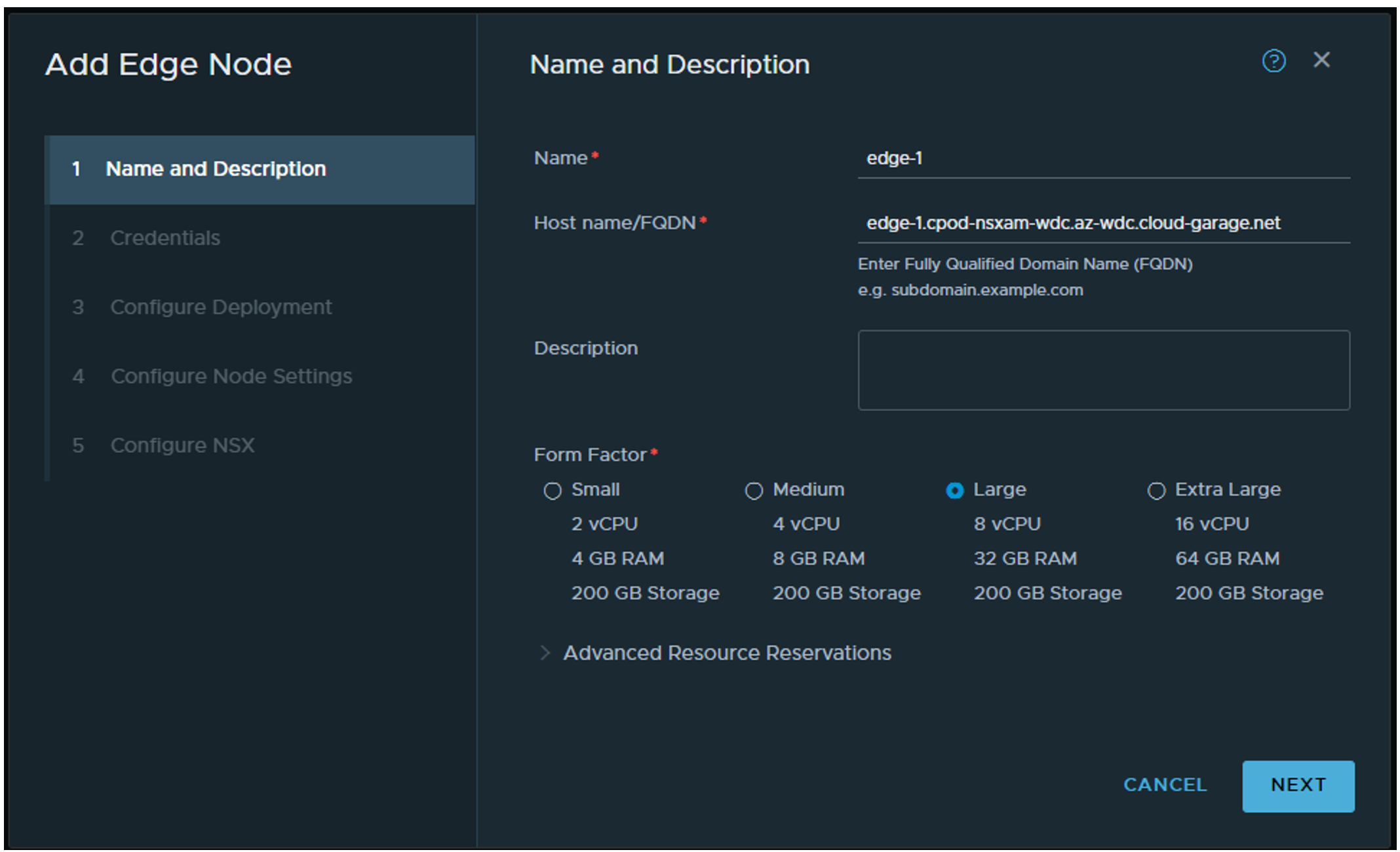
Give the edge a name, then fill in a FQDN name. Not sure if that part have to be actually registered in DNS, but it probably does do any harm if you decide to. Choose a form factor. When using Tanzu it can be potentially many virtual services so you should at least go with Large. You can find more sizing recommendation on the VMware official NSX docs page. Next
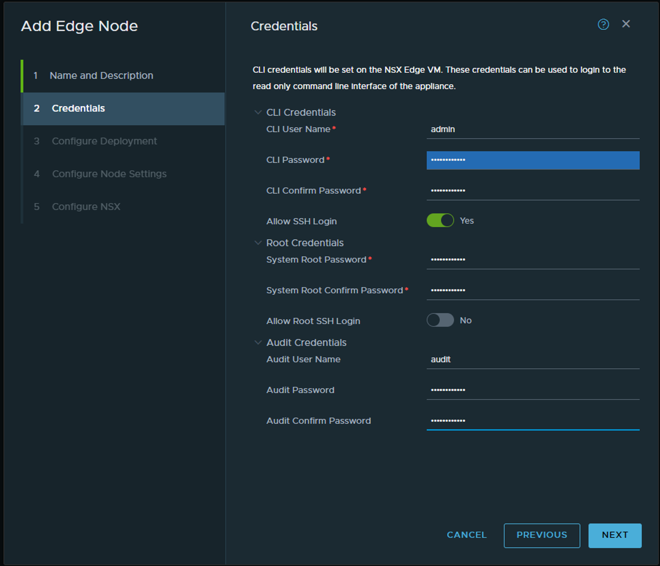
Fill inn your username and passwords (if you want easier access to SSH shell for troubleshooting purposes enable SSH now).
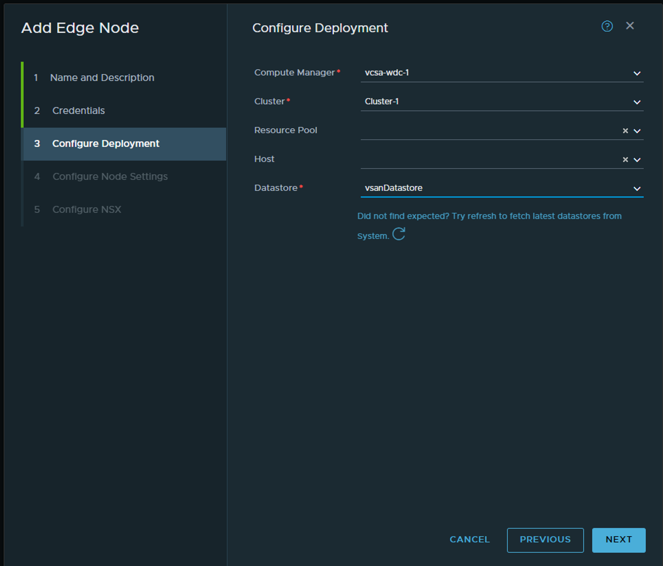
Select your vCenter, cluster and datastore. The rest default.
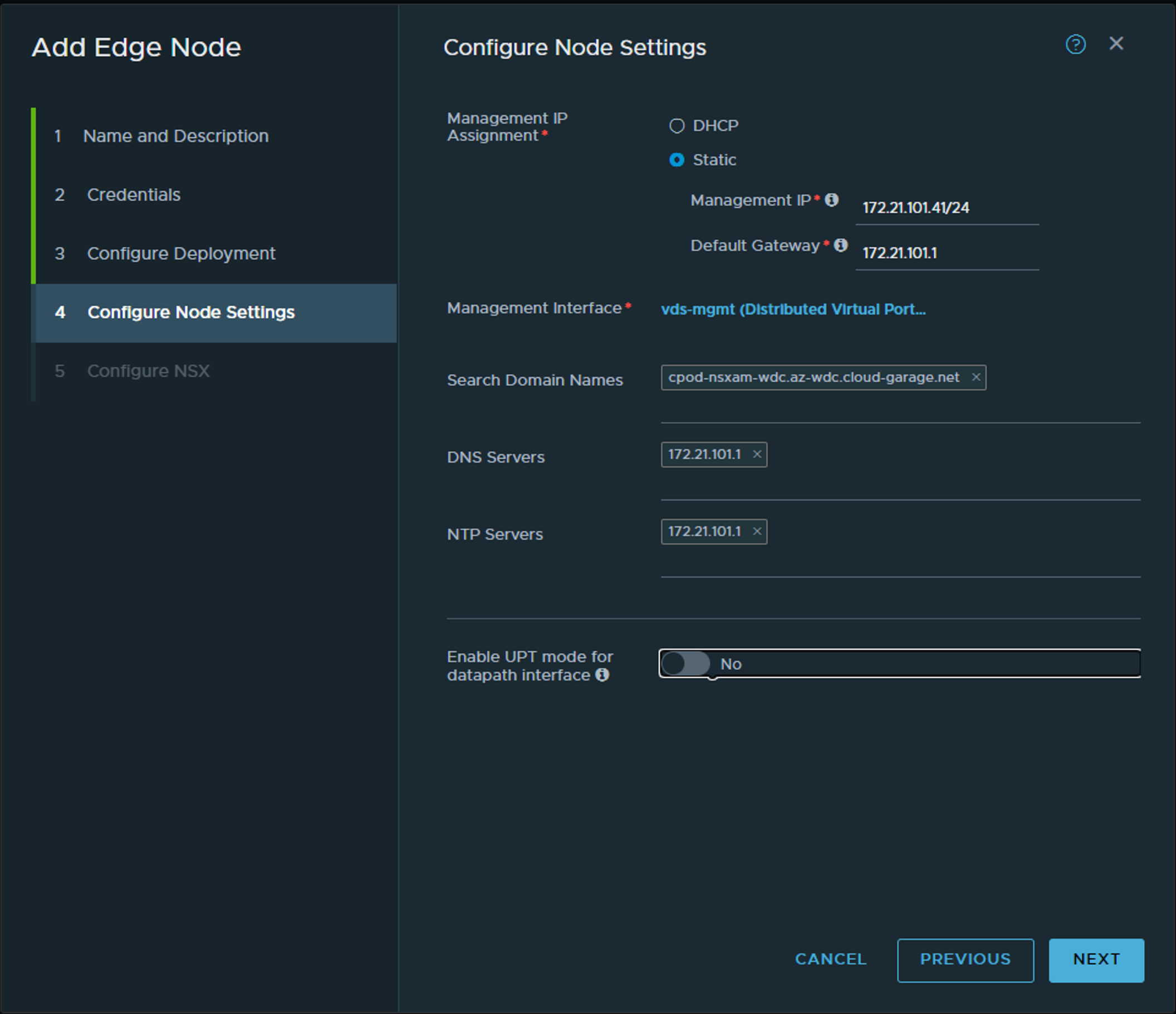
Configure the basics… This the part of the Edge that communicates with the NSX manager. Next we will configure the networking part that will be used for the T0 uplinks and TEP.
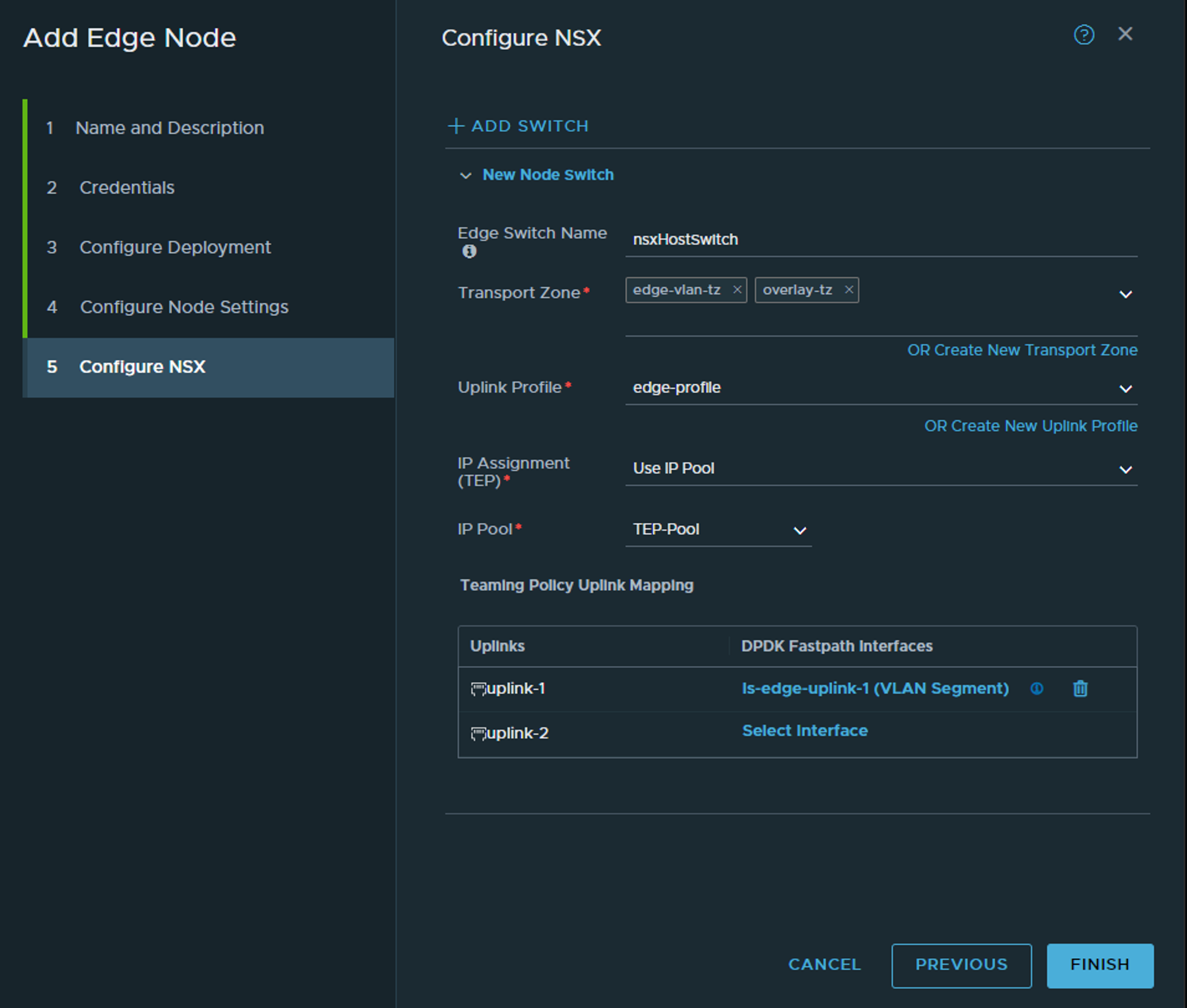
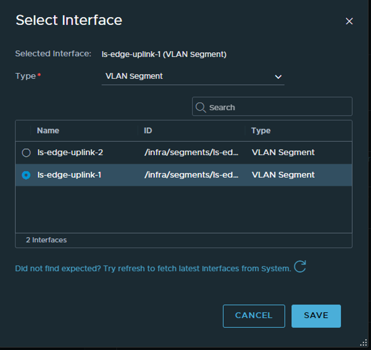
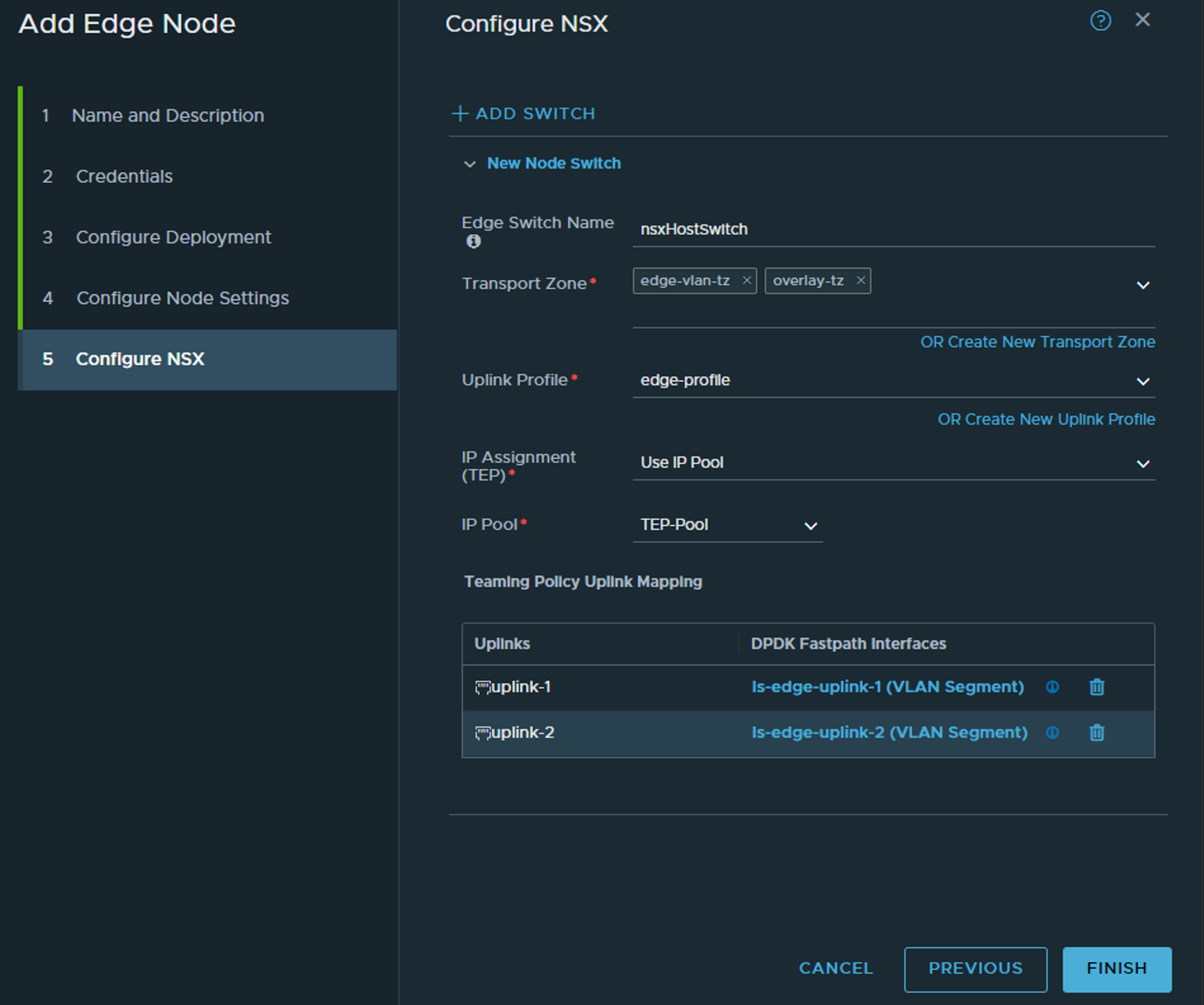
Here we select the transport zones for the Edge to be part of. Note, it should be part of your overlay transport zone but not part of the host vlan transport zone. Here we have defined a Edge vlan transportzone to be used. This is the transport zone where the segment for the T0 to be created in. One of the reason is that we dont want the segment for the T0 to be visible for the host for potentially other workloads, and the segment is actually created in the Edge, thats where the T0 is realised (The SR part of the T0). Then we select the edge-profile we created earlier, the same IP pool as the hosts. Under uplinks we select the respective vlan segments uplink 1 and 2 created earlier.
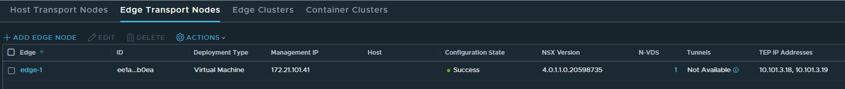
Then finish. It should take a couple of minutes to report ready in the NSX manager ui.
Status when ready for duty:
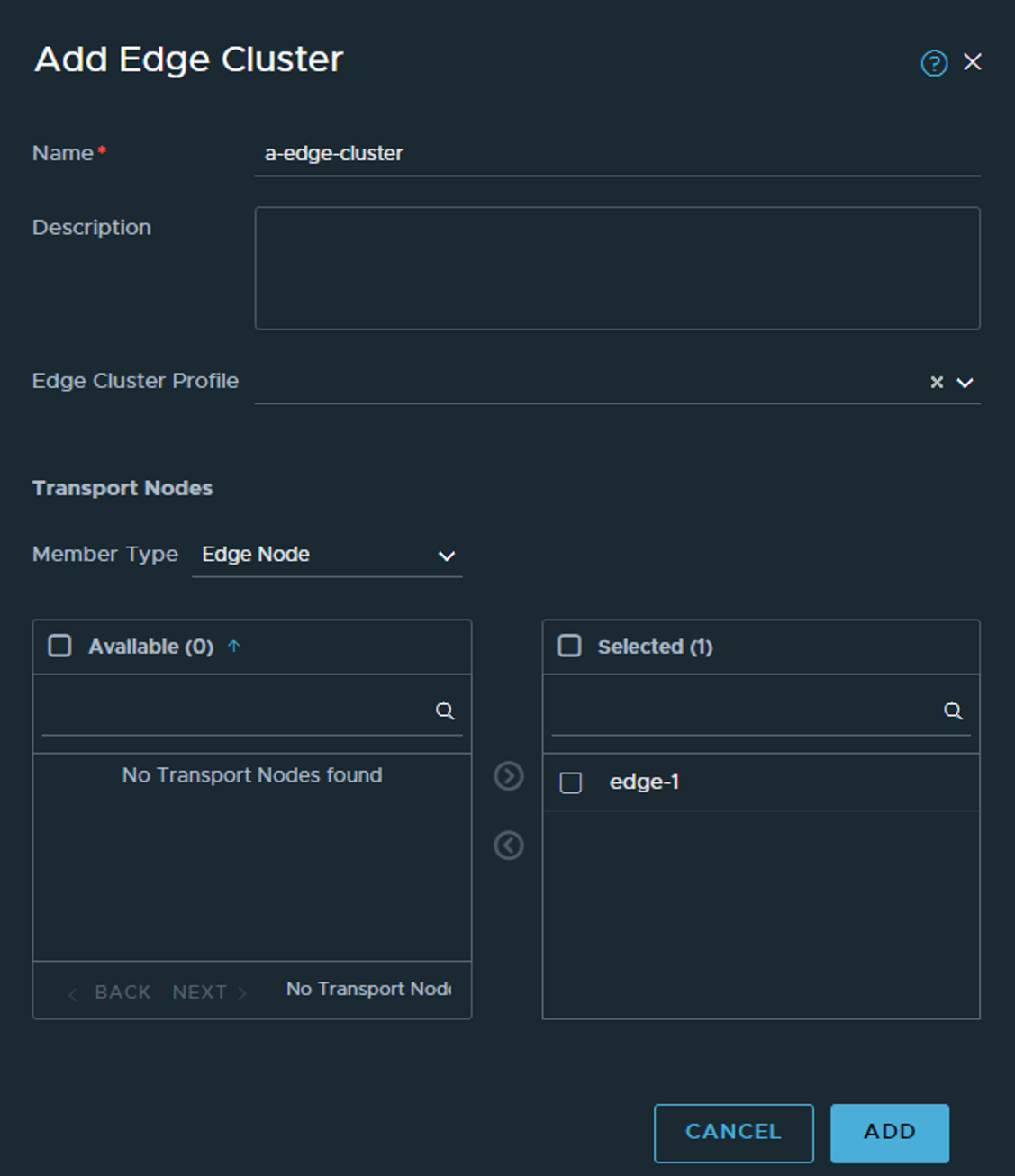
There should also be some activity in vCenter deploying the edge. When ready head over to Edge Clusters and create a cluster to put the Edge in. We need an Edge cluster and the edges in an edge cluster before we can do anything with them, even if we only deploy one edge (labs etc).
The T0 #
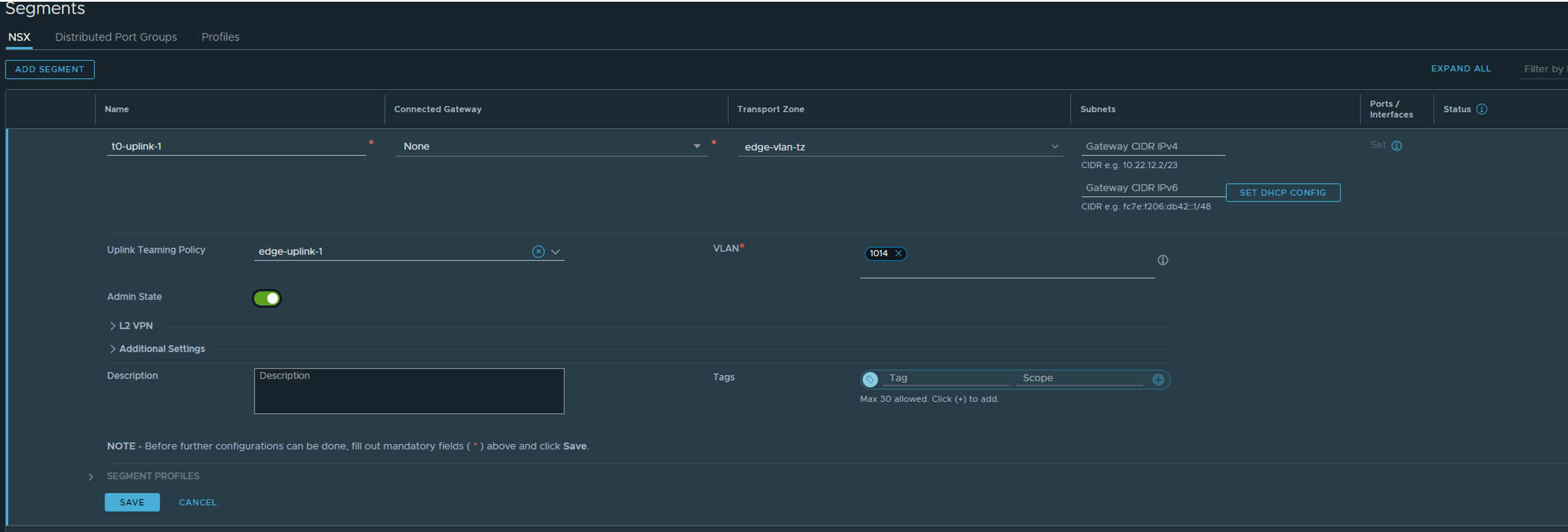
Now that at least one Edge is up, we should create a T0 so we can make some external connectivity happen (even though NSX have its own networking components and we can create full L3 topology, we cant talk outside NSX from overlay without the Edges). Head over to Network and create a VLAN segment. This time the segment should be placed in the edge-vlan-tz as it is use for T0 uplinks only. Select teaming policy and correct vlan for the T0 uplink 1. I will only use 1 uplink in my lab so I will only create 1 segment for this, I only have 1 upstream router to peer to also.
Next is heading over to Tier-0 and create a T0:
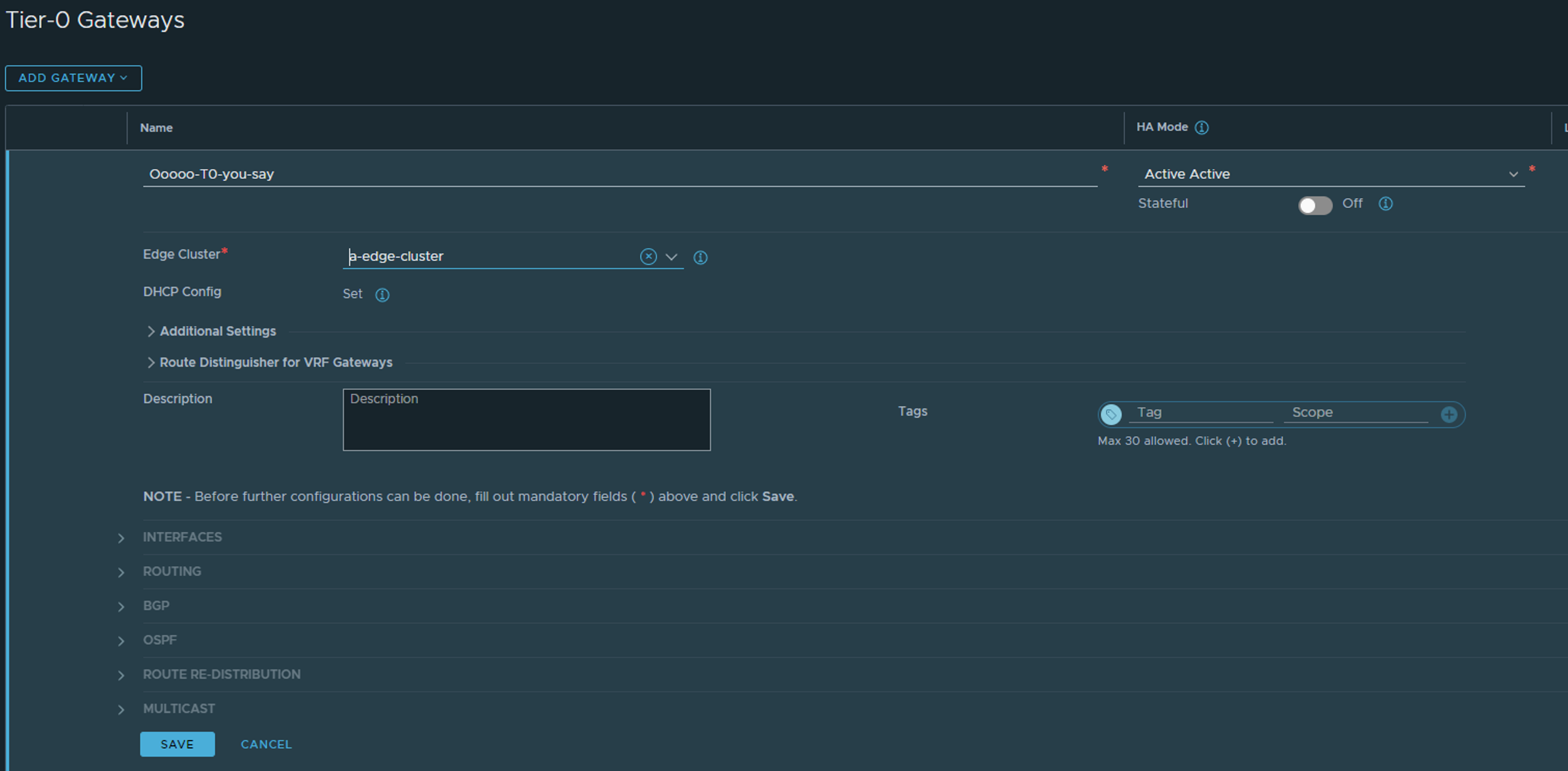
The selection is very limited at first, so give it a name and select HA mode, and edge cluster (the one that we created above).
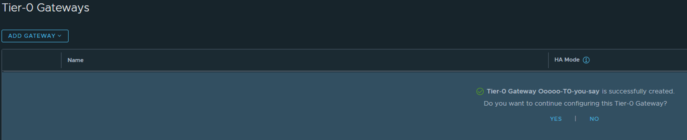
Click save and yes to continue edit:
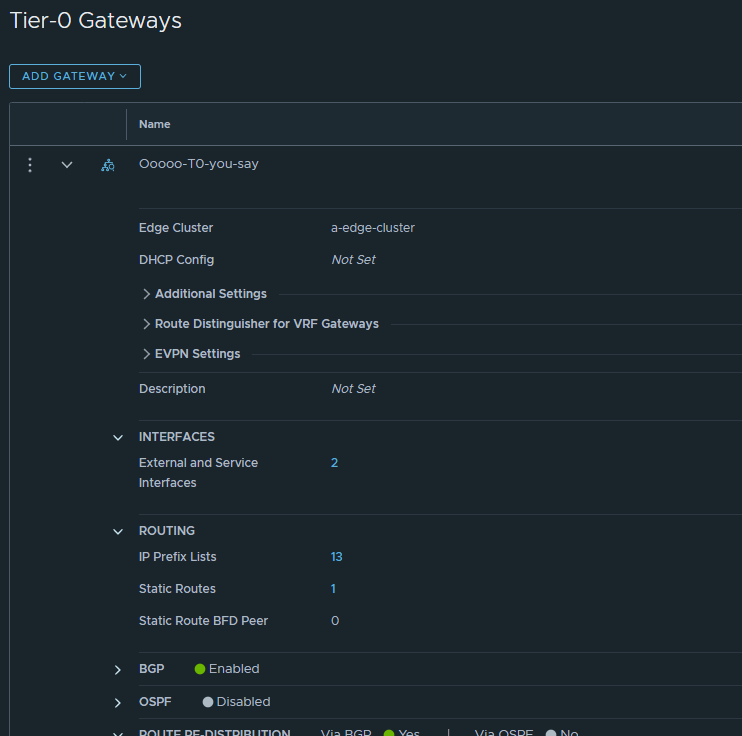
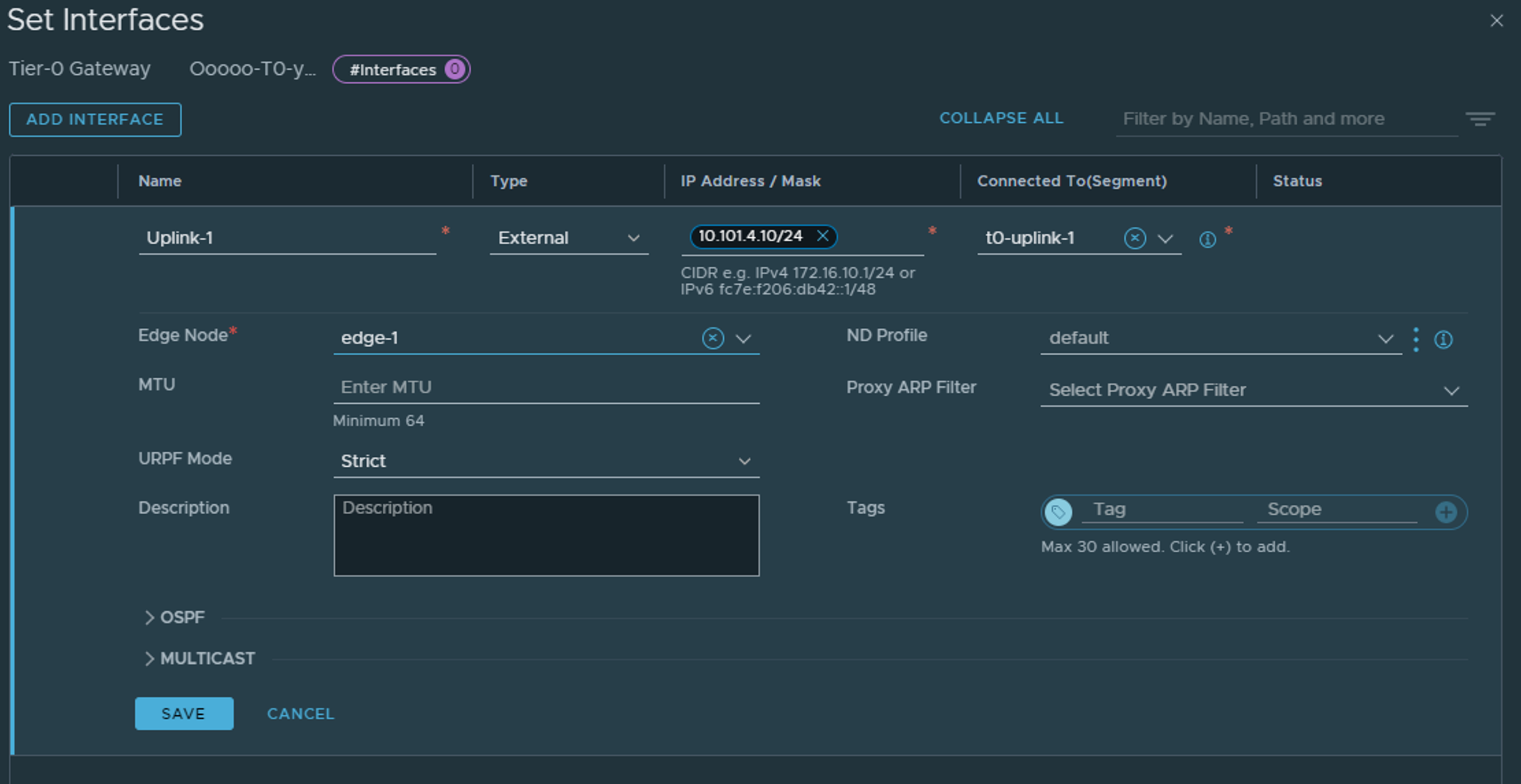
Now we need to add the interface(s) to the T0. The actual interfaces will be residing on the Edges, but we need to define them in the T0. Click on the 0 under Interfaces (its already two interfaces in the screenshot below).
Give the interface a name, choose type External, give it the correct IP address to peer with the upstream router, and select the Edge VLAN segment created earlier which maps to the correct uplink (1 or 2). Then select the Edge node that shall have this interface configured.
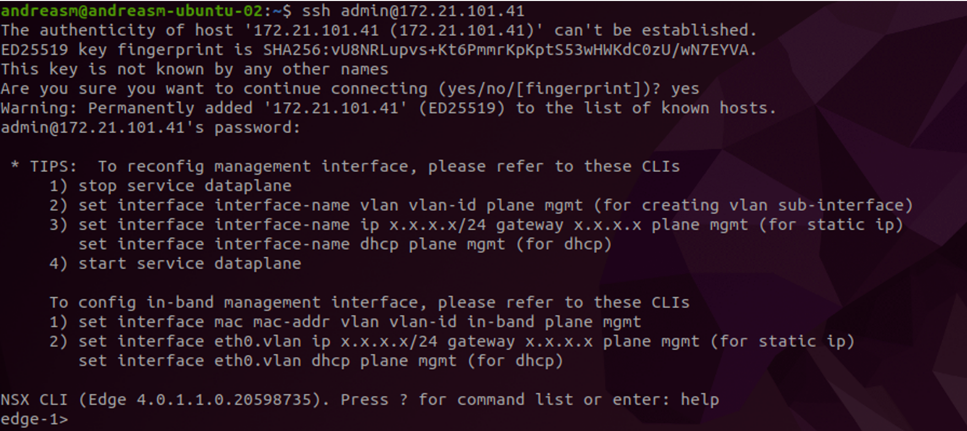
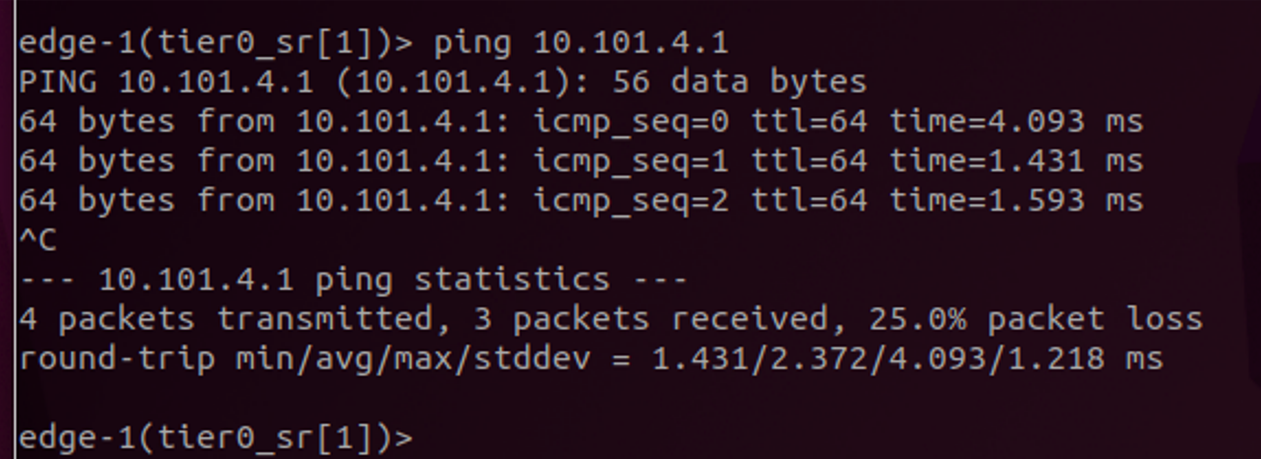
Click save. Now as an optional step SSH into the Edge selected above, go the correct vrf and ping the upstream router.
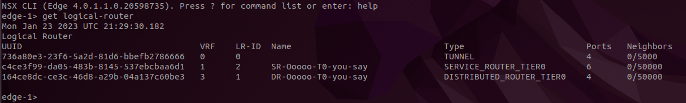
Get the correct VRF (we are looking for the SR T0 part of the T0)
Enter the vrf by typing vrf and the number, here it is vrf 1.
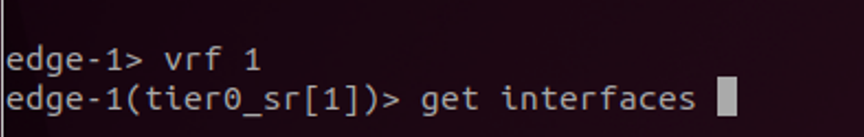
Listing the interface with get interfaces one should see the interface we configured above, and we can ping the upstream router to verify L2 connectivity.
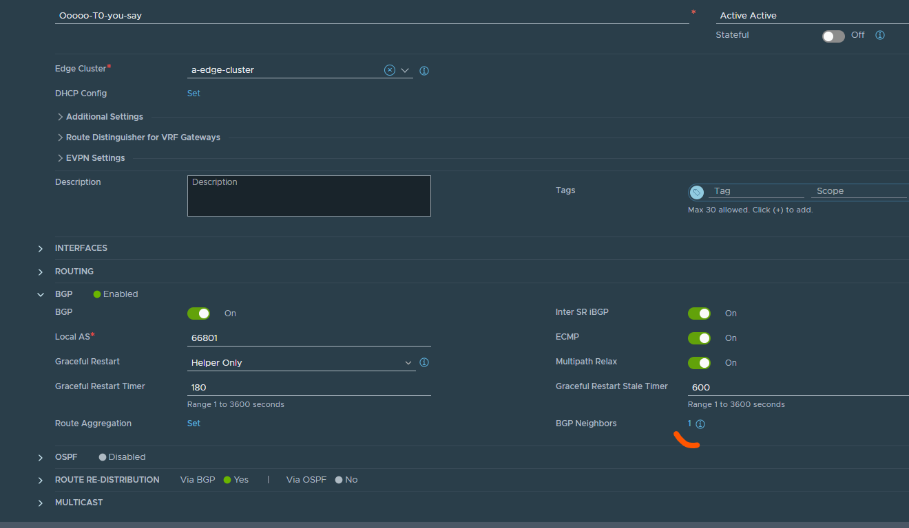
Good, now configure BGP. Expand BGP in your T0 settings view (same place as we configure the interface) adjust your BGP settings accordingly. Click save, enter again and add your BGP peers/neighbors bly clicking on neighbors.
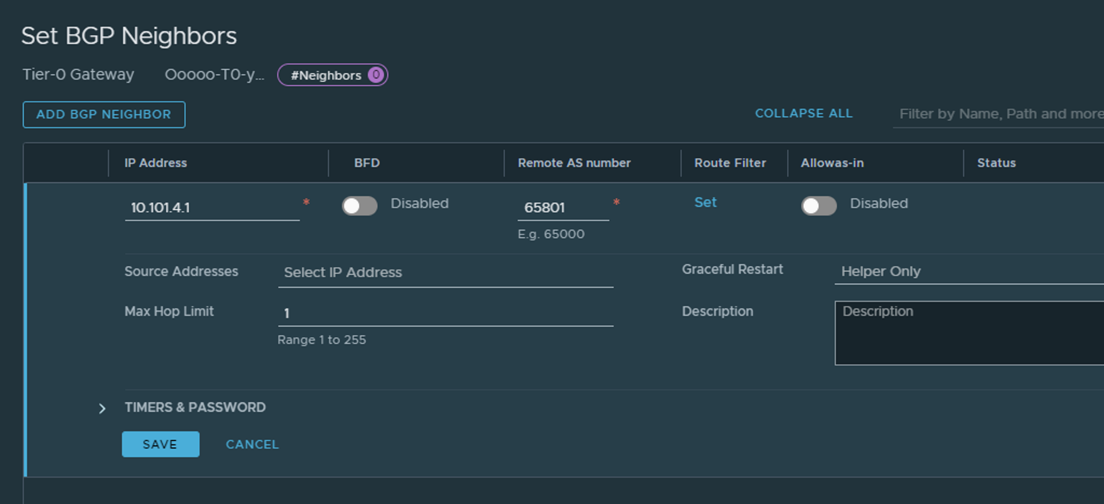
Add the IP to the BGP peer you should use and adjust accordingly, like AS number. Click Save
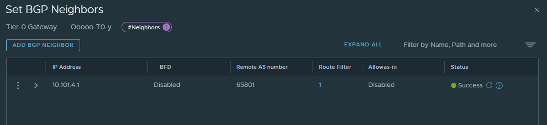
It will become green directly, then if you click refresh it will become red, then refresh again it should be green again if everything is correct BGP config wise on both sides. Clicking on the (i) will give you the status also:
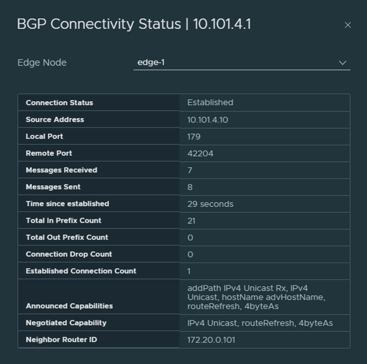
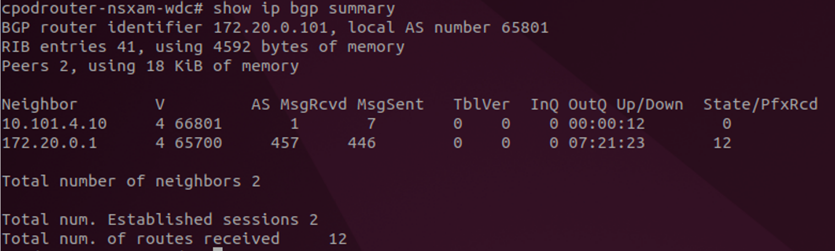
From your upstream routes you should see a new neighbor established:
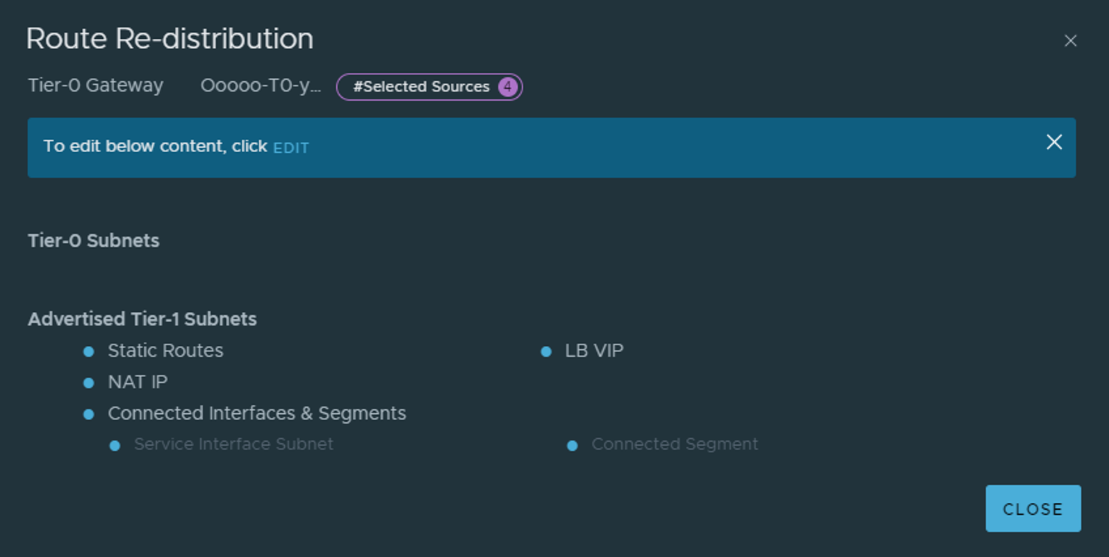
The last step on the T0 now is to configure it which networks it should advertise on BGP. That is done under Route re-distribution. In a Tanzu setup we need to advertise NAT, connected and LB VIP from our T1s. That is because Tanzu or NCP creates NAT rules, it creates some LB VIPS and we should also be able to reach our other Overlay segments we create under our T1 (which we have not created yet).
Now that T0 is configured and peering with the upstream router, I can create segments directly under the T0, or create T1s and then segments connected to the T1 instead. If you do create segments directly attached to the T0 one must configure route advertisement accordingly. As the config above is not advertising any networks from T0, only T1.
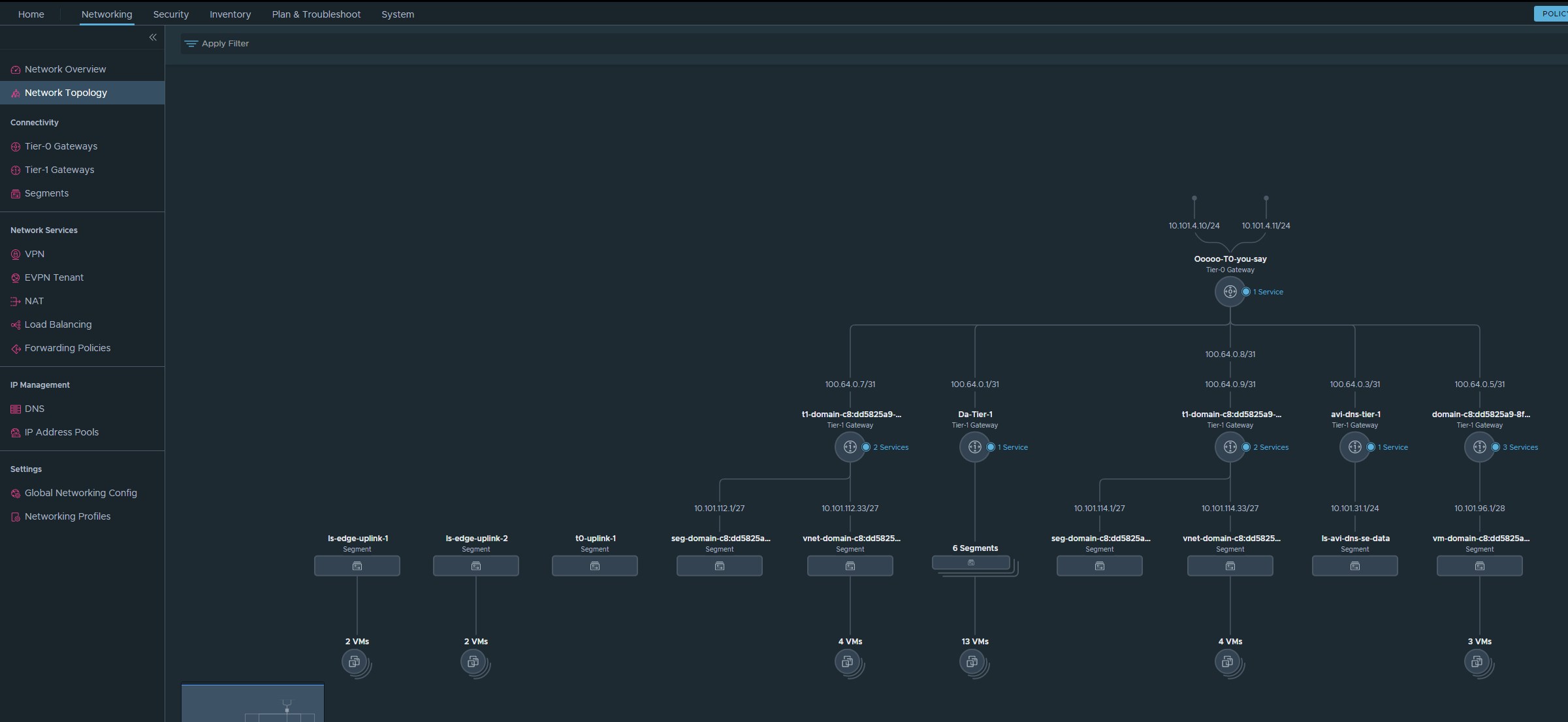
In NSX there is a neat map over the Network Topology in NSX:
Deploy Tanzu with NSX #
Now that networking with NSX is configured and the foundation is ready. Its time to deploy the Supervisor cluster, or enable WCP, Workload Management. Head over to the hamburger menu in top left corner in your vCenter and select * Workload Management*
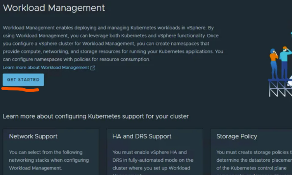
Click on Get Started
Then follow the wizard below:
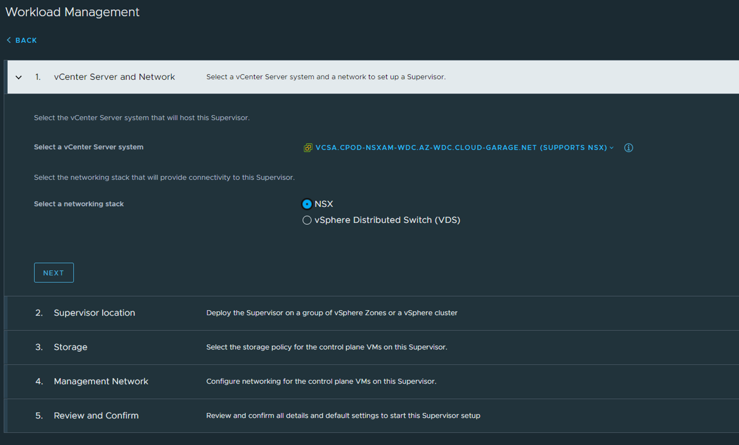
Select NSX and Next
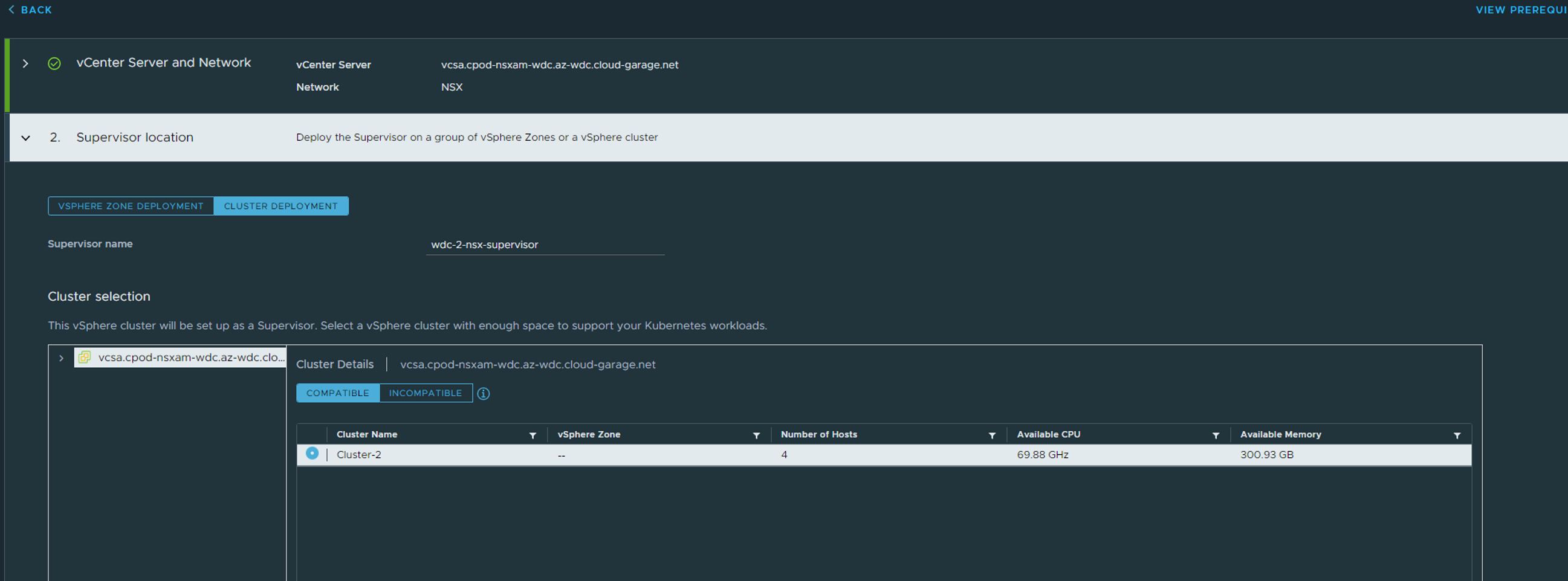
Select Cluster Deployment, choose your vCenter cluster, give the supervisor a name and below (not in picture above) enter a zone name.
Next
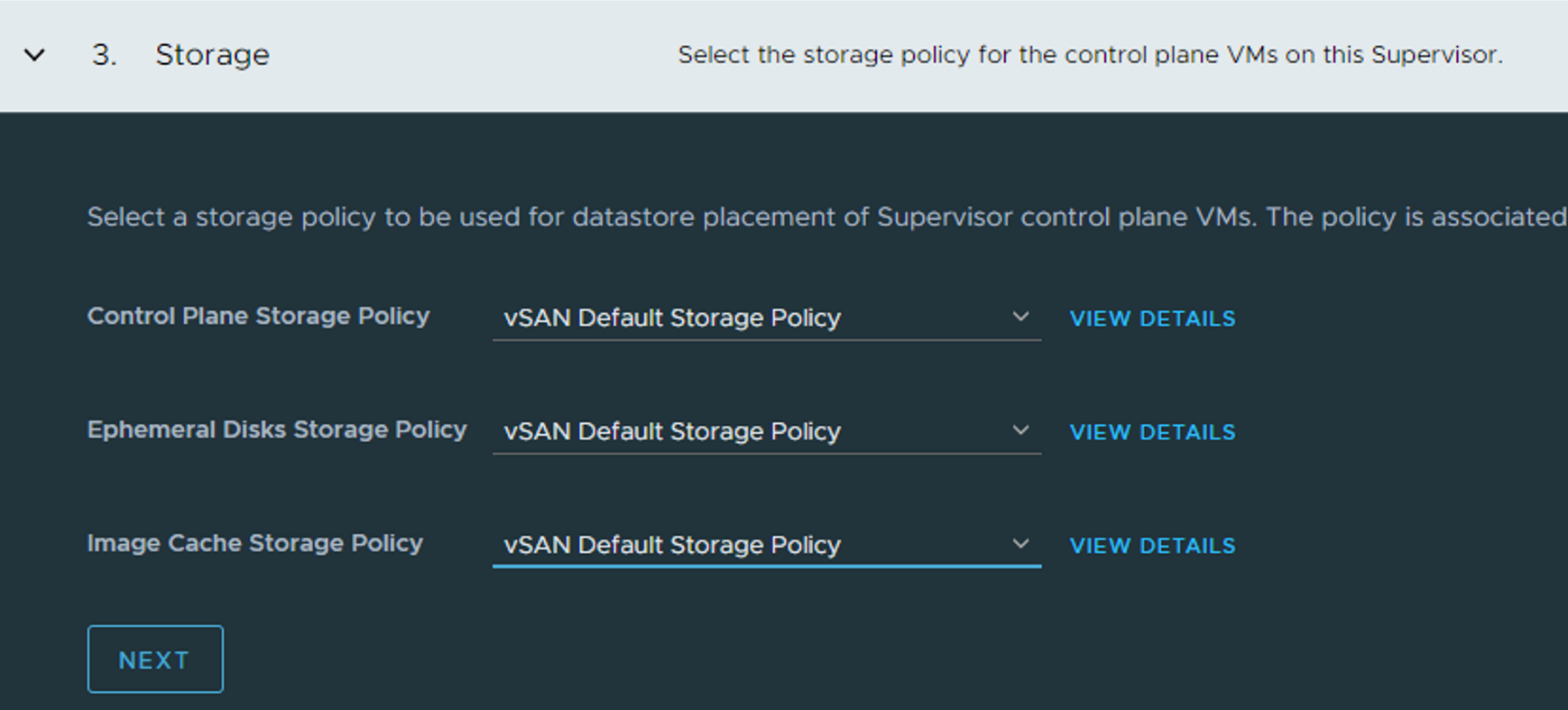
Select your storage policies, Next
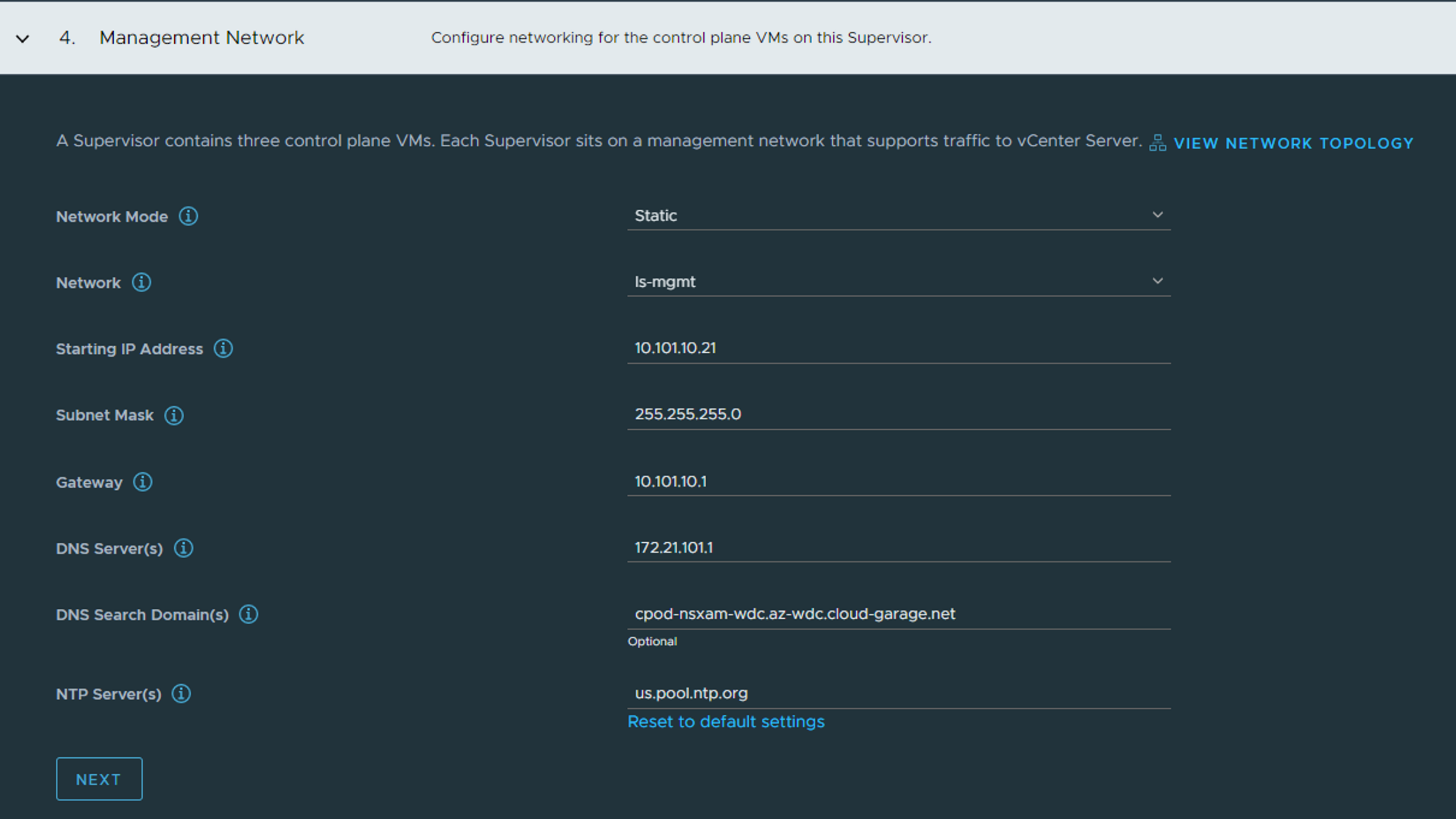
In Step 4 - Management Network we configure the network for the Supervisor Control Plane VMs. In my lab I have already created an overlay segment I call ls-mgmt with cidr 10.101.10.0/24 and gateway 10.101.10.1. So I will place my Supervisors also there. Not using DHCP, but just defining a start IP. The Supervisors will consist of three VMs, and a cluster IP. But it will use 5 IP addresses in total in this network. DNS, Search Domains and NTP should be your internal services. In screenshot above I have used an external NTP server. NEXT
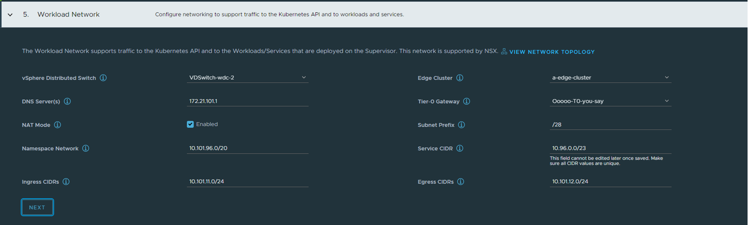
Above I define the workload network, which the supervisor control plane vms also will be part of, but also for the vSphere Pods. This a default workload network where your TKC cluster can be deployed in (if not overriden when creating a vSphere namespace (later on that topic) ). Select the VDS you have used and configured for NSX. Select your Edge cluster. Add your DNS server(s), select the T0 router you created earlier in NSX. Then leave NAT-Mode enabled, we can create vSphere namespaces later where we override these settings. Then you define the Namespace Network. This is the network your vSphere pods will use, the workload network interface of the Supervisor ControlPlane Nodes, and your TKC cluster nodes. The CIDR size define how many IPs you will have available for your TKC cluster nodes, meaning also the total amount of nodes in this workload network. But dont despair, we can create additional vSphere namespaces and add more networks. So in the above example I give it a /20 cidr (unnecessary big actually, but why not). This Namespace Network will not be exposed to the outside world as NCP creates route-map rules on the T0 not allowing these to be advertised (we have NAT enabled). The Service CIDR is Kubernetes internal network for services. When we deploy a TKC cluster later we define other Kubernetes cluster and pod cidrs. Define the Ingress CIDR, this is the IP address range NCP will use to carve out LoadBalancer VIPs for the Kubernetes API endpoints, for the Supervisor Control Plane, the TKC clusters K8s Api endpoint and even the Service Type LoadBalancer services you decide to created. So all access TO the Supervisor Cluster API endpoint will be accessed through the IP address assigned from this CIDR. When we have NAT enabled it will also ask you to define a Egress CIDR which will be used by NSX to create SNAT rules for the worker nodes to use when communicate OUT. These NAT rules will be created automatically in NSX-T.
NEXT
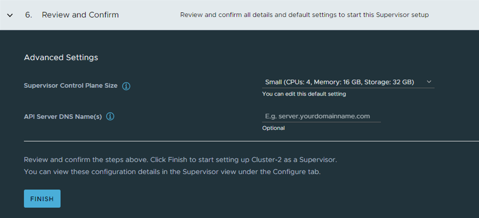
Select the size of your SVCP and give the SVCP API endpoint a name. This is something that can be registered in DNS when deployment is finished and we know the IP it gets.
Finish and wait. Its the same (waiting) process as explained here
If everything goes well we should have a Supervisor cluster up and running in not that many minutes. 20-30 mins?
When its done deploying you will see the green status here:
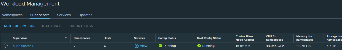
Notice the Control Plane Node Address, this is our endpoint IP being served by Avi loadbalancer and the one we use to interact with the Supervisor cluster to create workloads etc..
Enter the IP in your browser with https://10.101.11.2 and you should see this page:
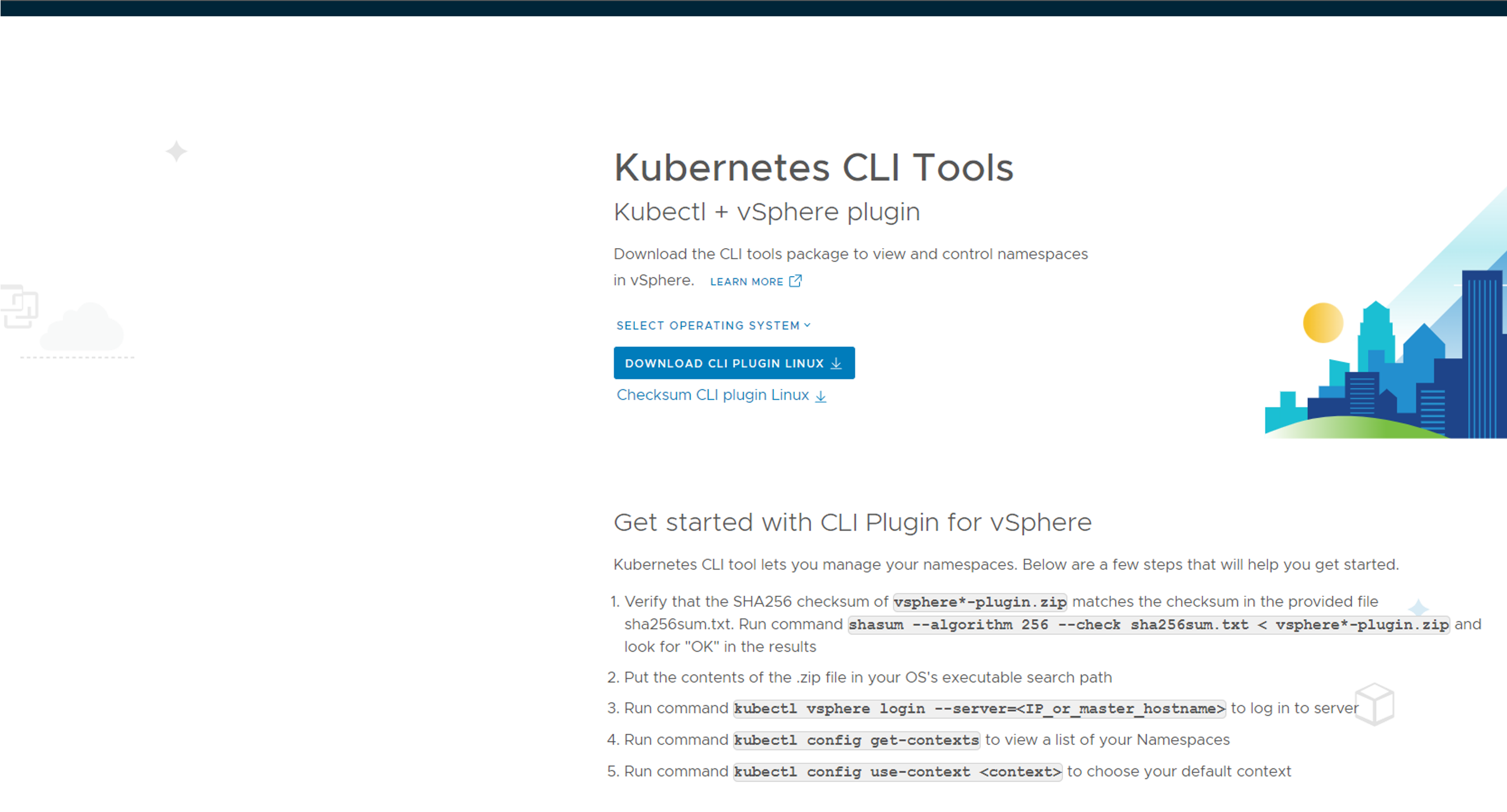
Download the cli tools for your operating system, deploy them so they are in your path. Will use both kubectl and kubectl-vsphere later on Next steps include creating namespace, deploy workload clusters.
NSX components configured by WCP/NCP #
Before heading over to next section, have a look in NSX and see what happended there:
Under Networks -> Segments you will notice networks like this:


Notice the gateway ip and CIDR. These are created for each vSphere Namespace, the cidr 10.101.96.1/28 is carved out of the CIDR defined in the “default” network when deploying WCP.
Under Networks -> T-1 Gateways you will notice a couple of new T1 routers being created:

Under Networks -> Load Balancing:
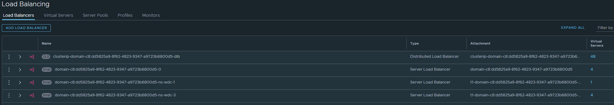
Here is all the L4 K8s API endpoints created, also the other Service Type Loadbalancer services you choose to expose in your TKC clusters.
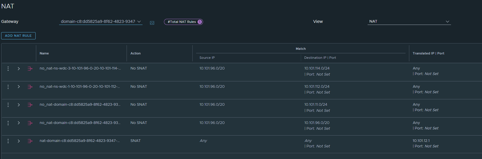
Under Networks -> NAT and the “domain” T1 there will be auto-created NAT rules, depending on whether NAT is enabled or disabled pr Namespace.
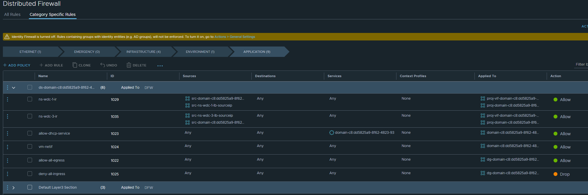
Then under Security -> Distributed Firewall there will be a new section:
vSphere Namespace #
When Supervisor is up and running next step is to create a vSphere Namespace. I will go ahead and create that, but will also use the “override network” to create a separate network for this Namespace and also disable NAT as I want to use this cluster for Antrea Egress explained here.
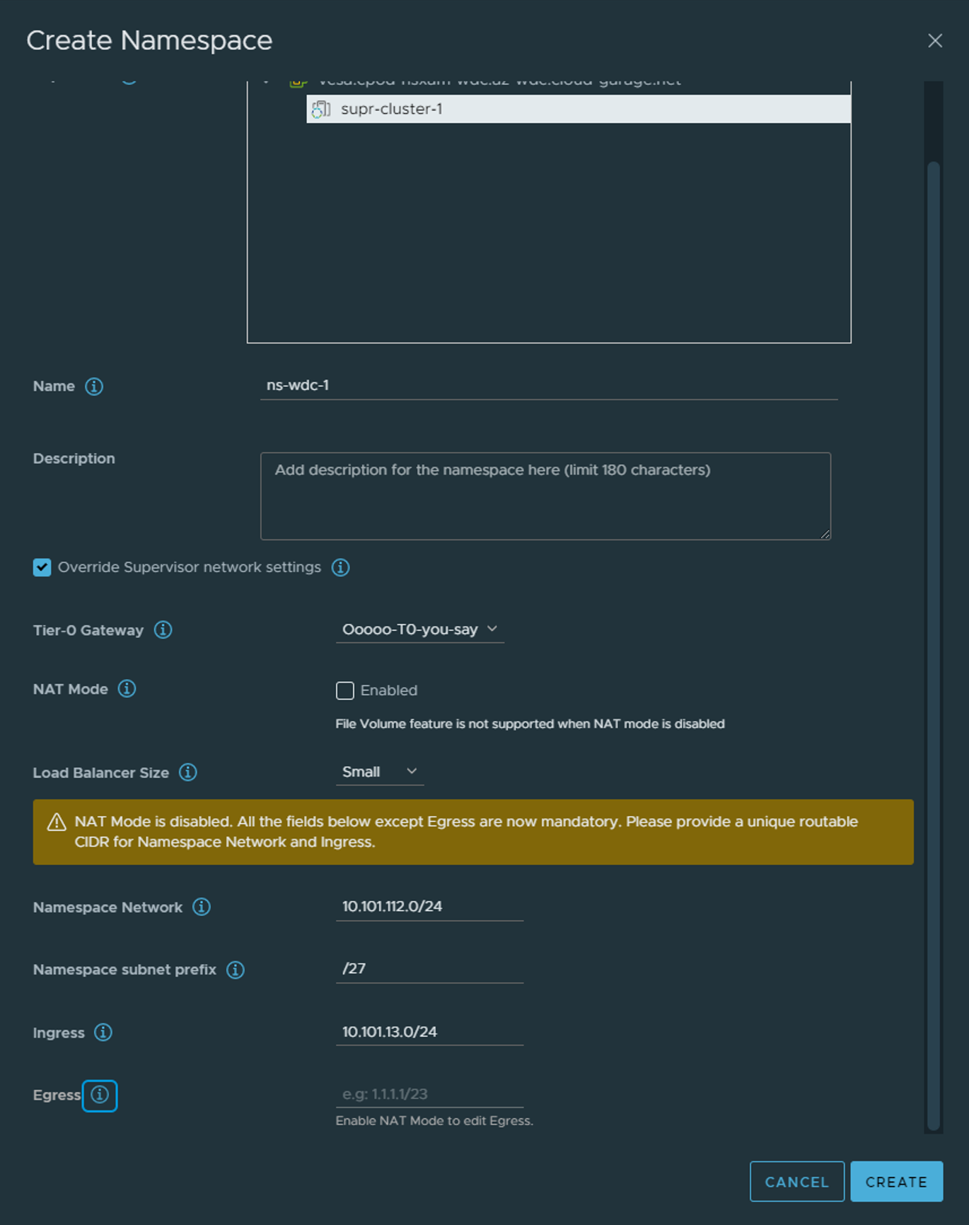
A vSphere is a construct in vSphere to adjust indidivual access settings/permissions, resources, network settings or different networks for IP separation. Click on Create Namespace and fill in relevant info. I am choosing to Override Supervisor network settings.
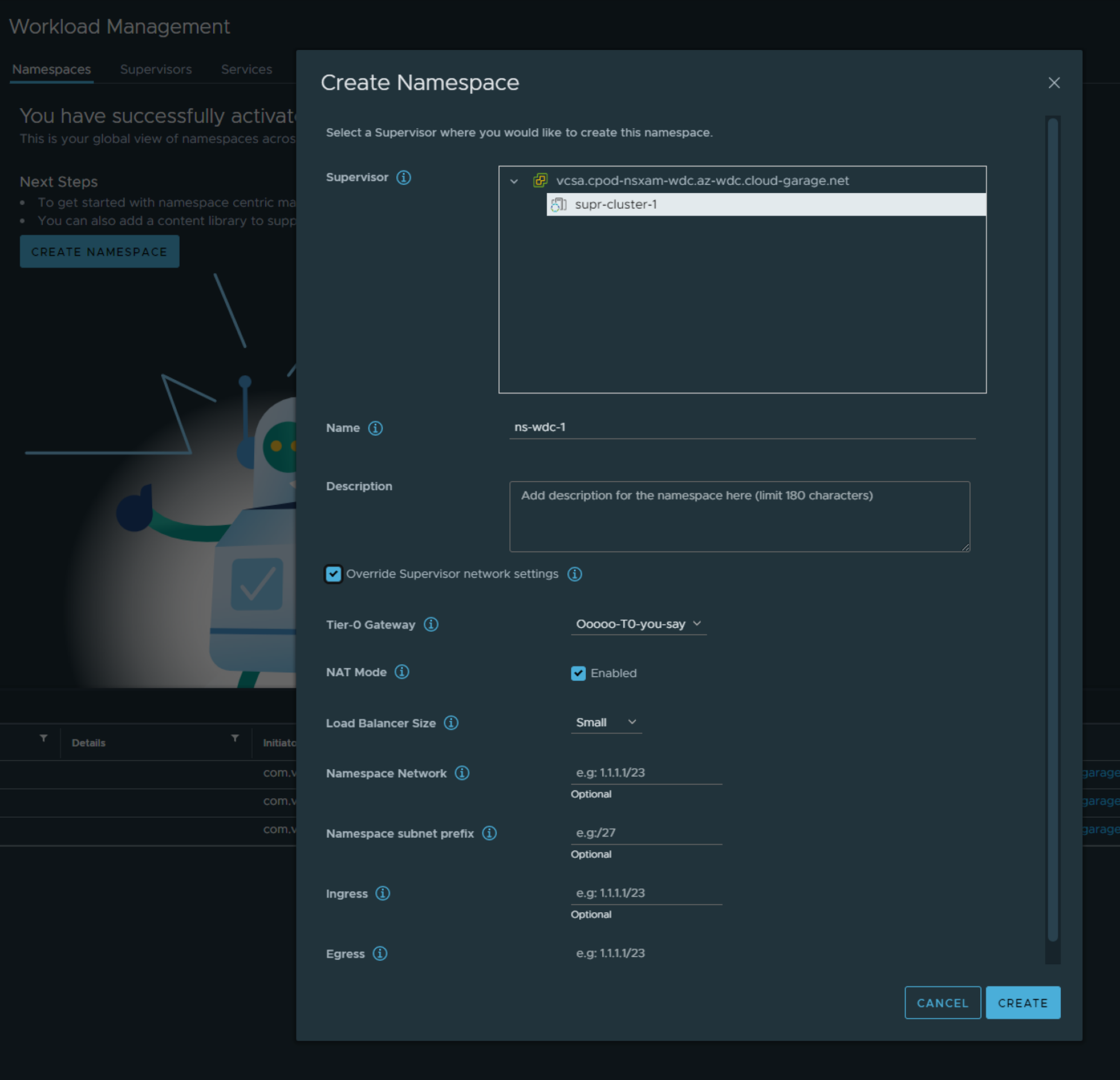
Notice when I disable NAT Mode there will no longer be a Egress IP to populate. Thats because the TKC nodes under this namespace will not get a NAT rule applied to them in NSX and will be communicating “externally” with their own actual IP address. Ingress will still be relevant as the NSX-T Loadbalancer will create the K8s API endpoint to reach the control plane endpoint your respective TKC clusters.
This option to adjust the networks in such a degree is a great flexibility with NSX. Tanzu with VDS does give you the option to select different VDS portgroups on separate vlans, but must be manually created, does not give you NAT, Ingress and Egress and VLAN/Routing must be in place in the physical environment. With NSX all the networking components are automatically created and it includes the NSX Distributed Firewall.
After the vSphere Namespace has been created it is the same procedure to deploy TKC clusters regardless of using VDS or NSX. So instead of me repeating myself and saving the environment for digital ink I will refere to the process I have already described here
Configure Avi as Ingress controller (L7) with NSX as L4 LB #
When using Antrea as the CNI in your TKC cluster (default in vSphere with Tanzu) make sure to enable NodePortLocal. This gives much better control and flexibility, follow how here and NodePortLocal explained here
Configure NSX cloud in Avi - network preparations #
As this guide is using NSX as the underlaying networking platform instead of VDS as this article is using, we also have the benefit of configuring the NSX cloud in Avi instead of the vCenter Cloud. This cloud do come with some additional benefits like automatic Security Group creation in NSX, VIP advertisement through the already configured T0, SE placement dataplane/data network on separate network and VRF context.
But before we can consume the NSX cloud we need to configure it. Assuming the Avi controller has already been deployed and initial config is done (username and password, dns, etc) log in to the controller and head over to Administration -> User Credentials:
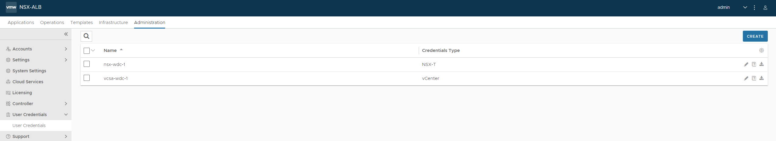
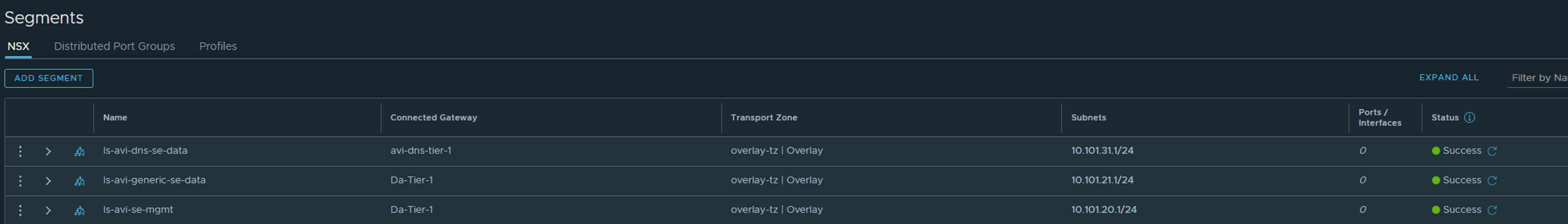
Add the credentials you want to use for both vCenter and NSX-T. The next step is involving NSX. Head over to NSX and create two new networks. One for SE management and one for SE dataplane (the network it will use to reach the backend servers they are loadbalancing). I will now just show a screenshot of three networks already created. One segment ls-avi-se-mgmt for SE mgmt, one segment ls-avi-generic-se-data for SE communication to backend pools, and one segment ls-avi-dns-se-data (I will get back to the last network later when enabling the Avi DNS service).
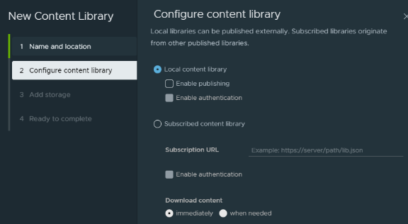
Then head over to vCenter and create a local Content Library and call it what you want.
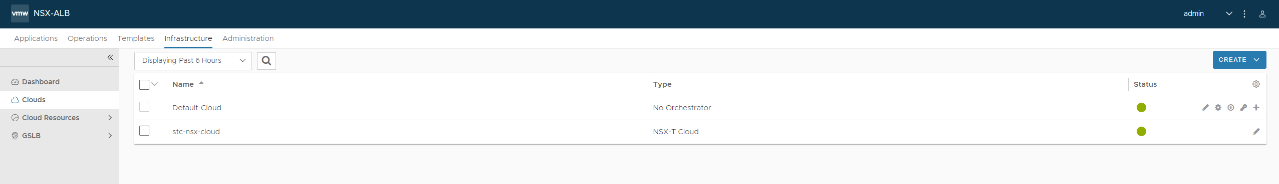
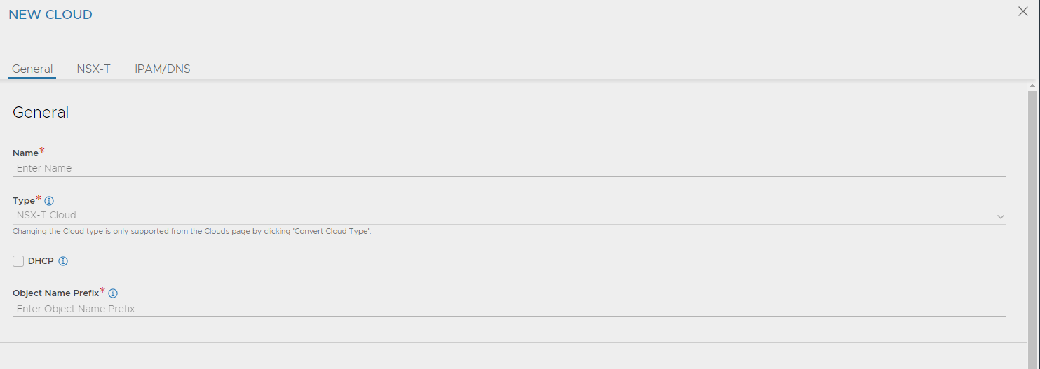
When networks and credentials have been created, back in the Avi gui head over to Infrastructure -> Clouds:
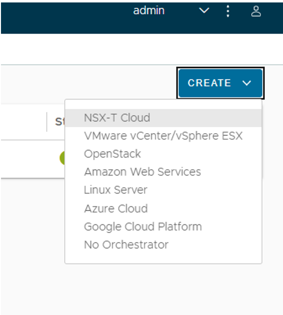
Click Create and select NSX-T
Start by giving the NSX cloud a meaningfull name and give a prefix name for the objects being created in NSX by Avi. If you have several Avi controllers using same NSX manager etc. Easier to identify when looking in the NSX manager ui:
Then proceed (scroll down if needed) to connect to you NSX manager:
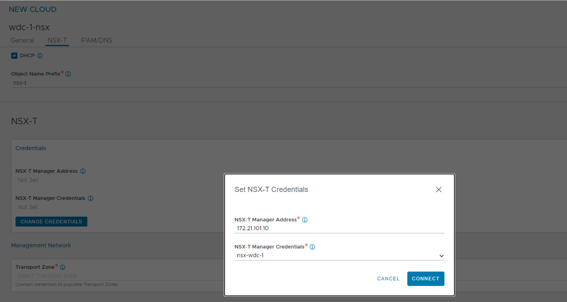
Enter the IP of your NSX manager, if you created a Cluster IP in the NSX manager use that one, and select the credentials for NSX manager create in the Avi earlier.
Connect.
!Note Before being able to continue this step we need to have defined some networks in NSX as explained above…
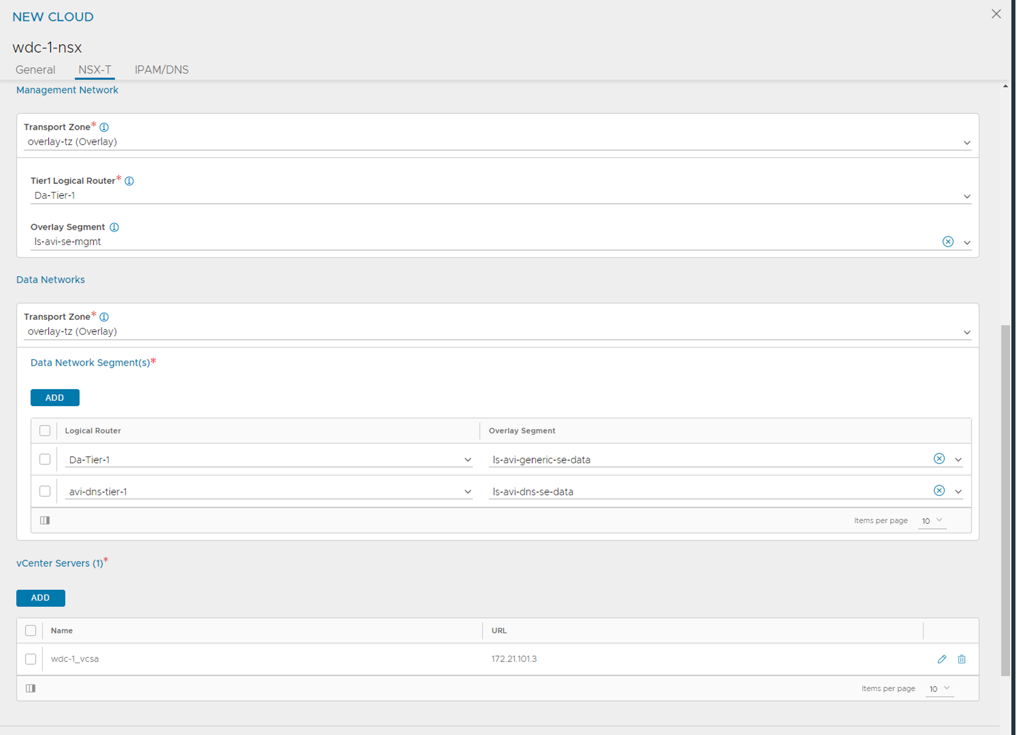
Fill in the Transport zone where you have defined the segment for the management network, select the T1 this segment is attached to and then the segment. This network is created in NSX for the SE management interface. Then go to Data Networks and select the Overlay Transport Zone where the ls-avi-generic-se-data segment is created the ADD the T1 router for this segment from the dropdown list and the corresponding segment. (Ignore the second netowork in the screenshot above.) Then under vCenter Server click add and fill in relevant info to connect the vCenter server your NSX manager is using.
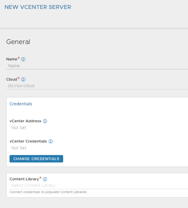
Give it a meaningful name, it will either already have selected your NSX cloud otherwise select it from the list. Then the credentials and the Content Library from the dropdown.
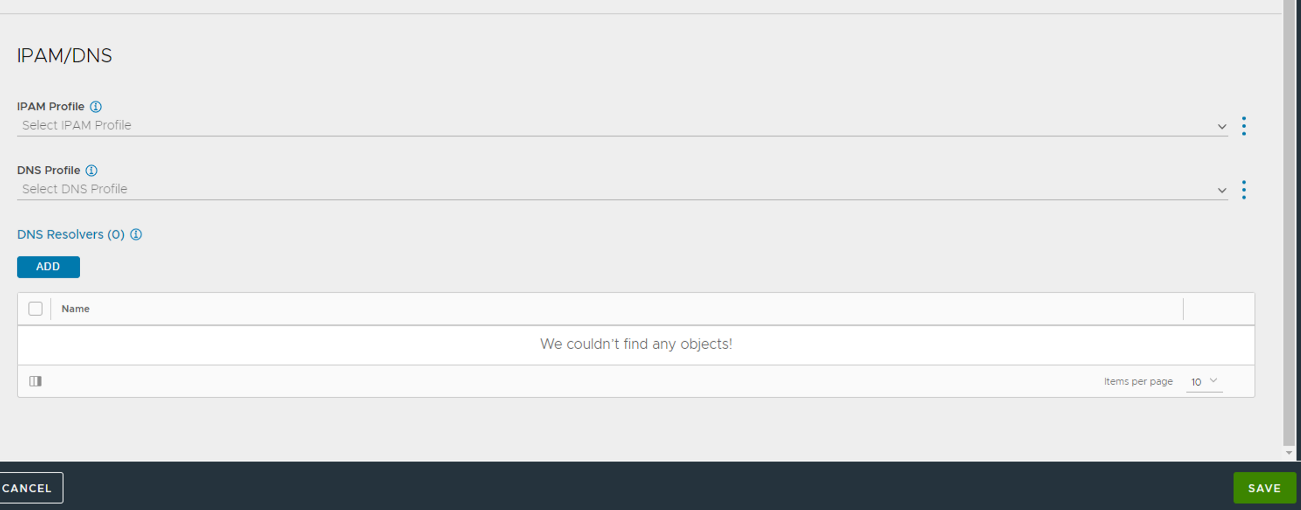
The last section IPAM/DNS we will fill out later (click save):
Now the cloud should be created.
SE Groups #
Head over to Cloud Resources -> Service Engine Groups and create a custom SE-group.
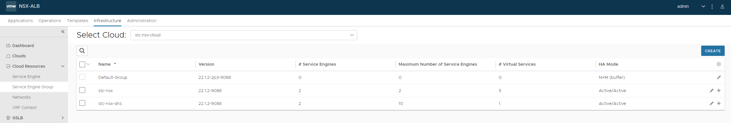
Select your newly created cloud from the dropdown list above next to Select Cloud. Click create blue button right side.
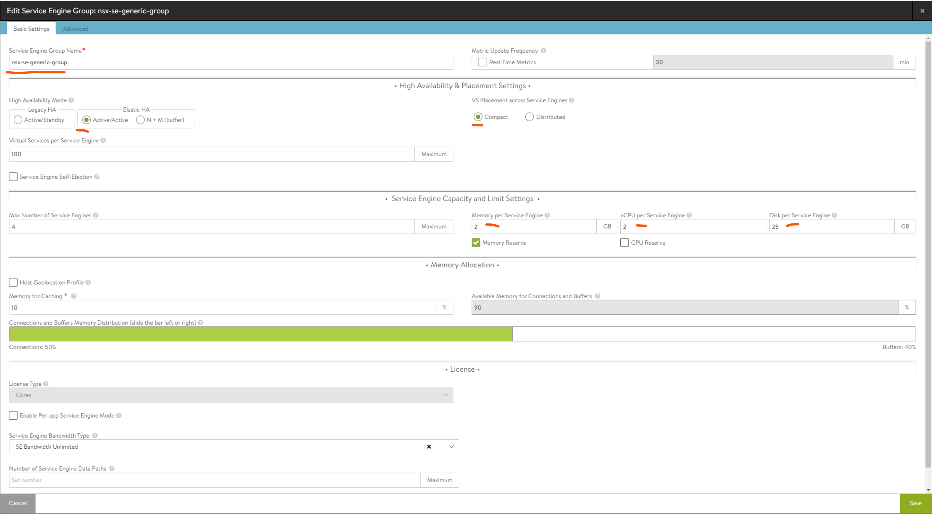
Change the fields marked by a red line. And optionally adjust the Max. Number of Service Engines. This is just to restrict Avi to not deploy too many SE’s if it sees fit. Adjust the Virtual Services pr Service Engine to a higher number than 10 (if that is default). This all comes down to performance.
Jump to advanced:
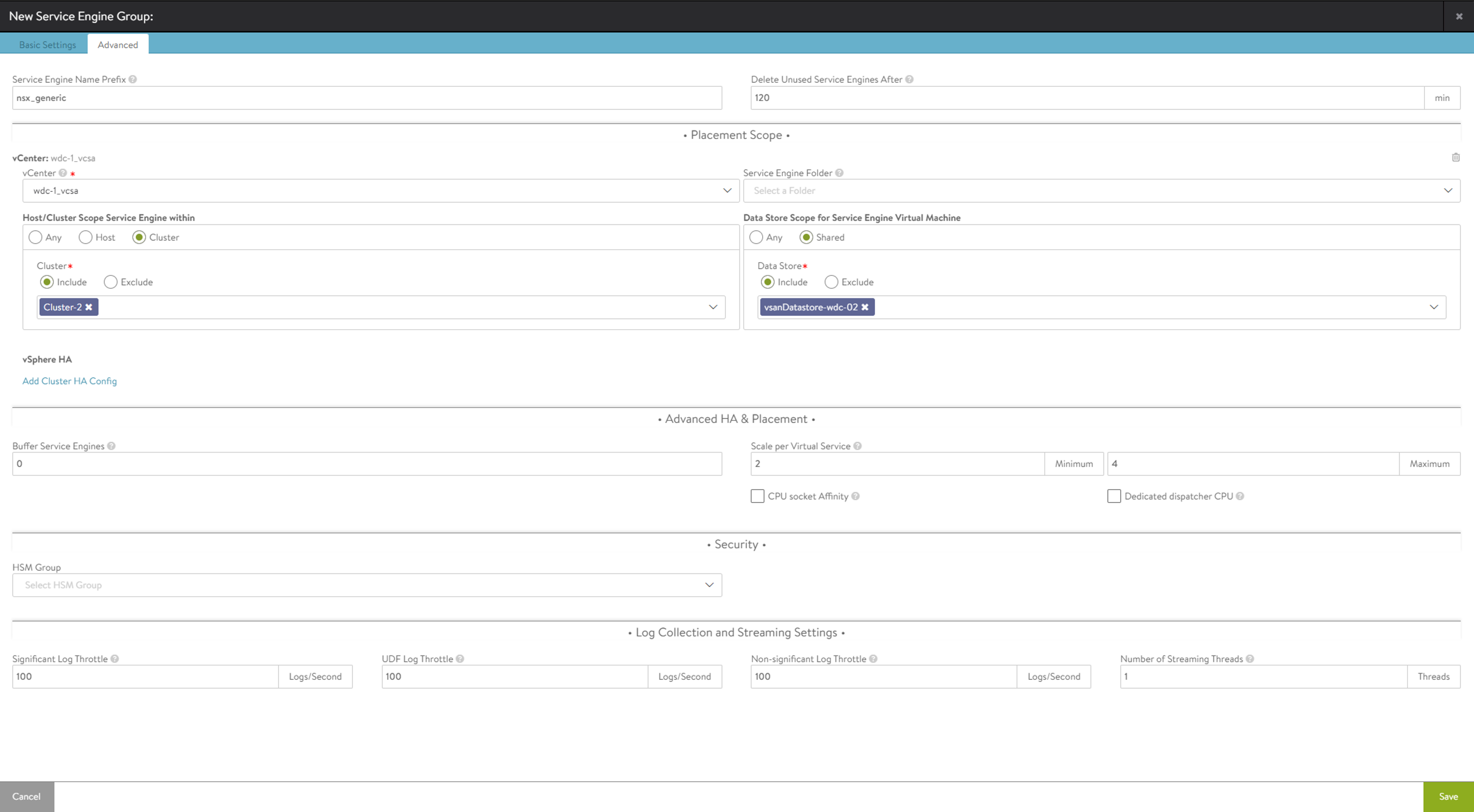
Change the Service Engine Name Prefix to something useful, then select the vCenter, cluster and datastore. Save
Avi Networks #
Now head over to Infrastructure -> VRF Contexts (below Service engine Groups) select correct cloud from dropdown and add a default gateway for the SE dataplane network.
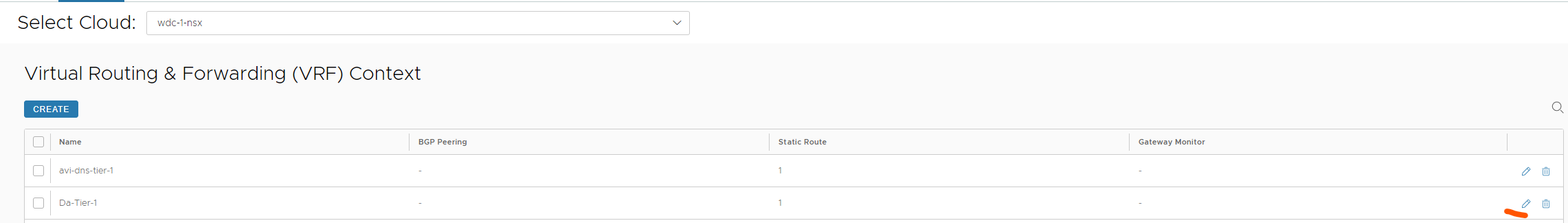
Click the pencil
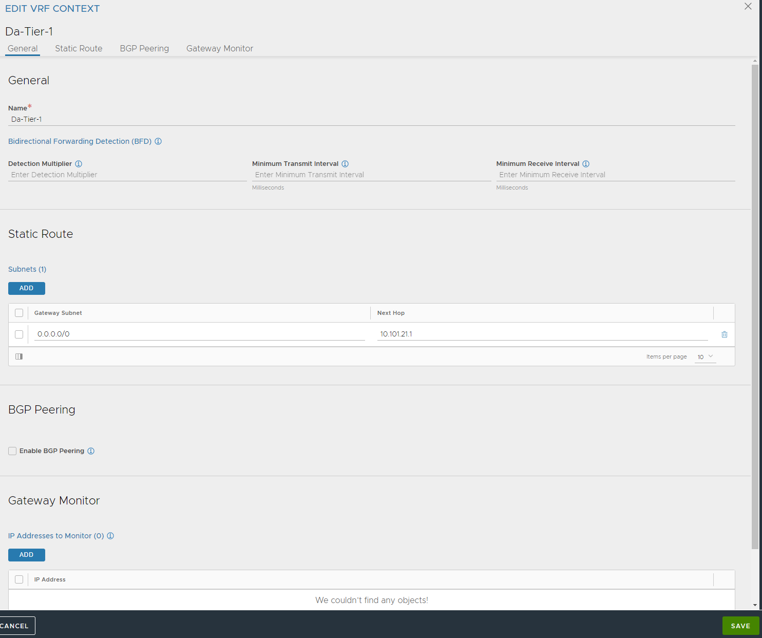
Add a default route under Static Route and point to the gateway used for the SE dataplane ls-avi-generic-se-data . This is used for the SE’s to know where to go to reach the different pools it will loadbalance.
Next we need to define the different networks for the SE’s to use (the dataplane network). Head over to Infrastructure -> Networks (again select correct cloud from dropdown)
If there is workload running in these networks they can already be auto-detected, if not you need to create them.
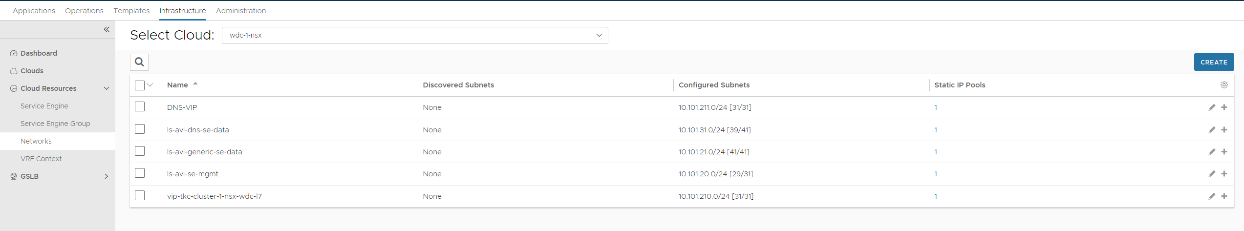
In my lab I rely on Avi as the IPAM provider for my different services, a very useful feature in Avi. So the two networks we need to create/and or edit is the ls-avi-se-mgmt and the ls-avi-generic-se-data
First out is the ls-avi-se-mgmt
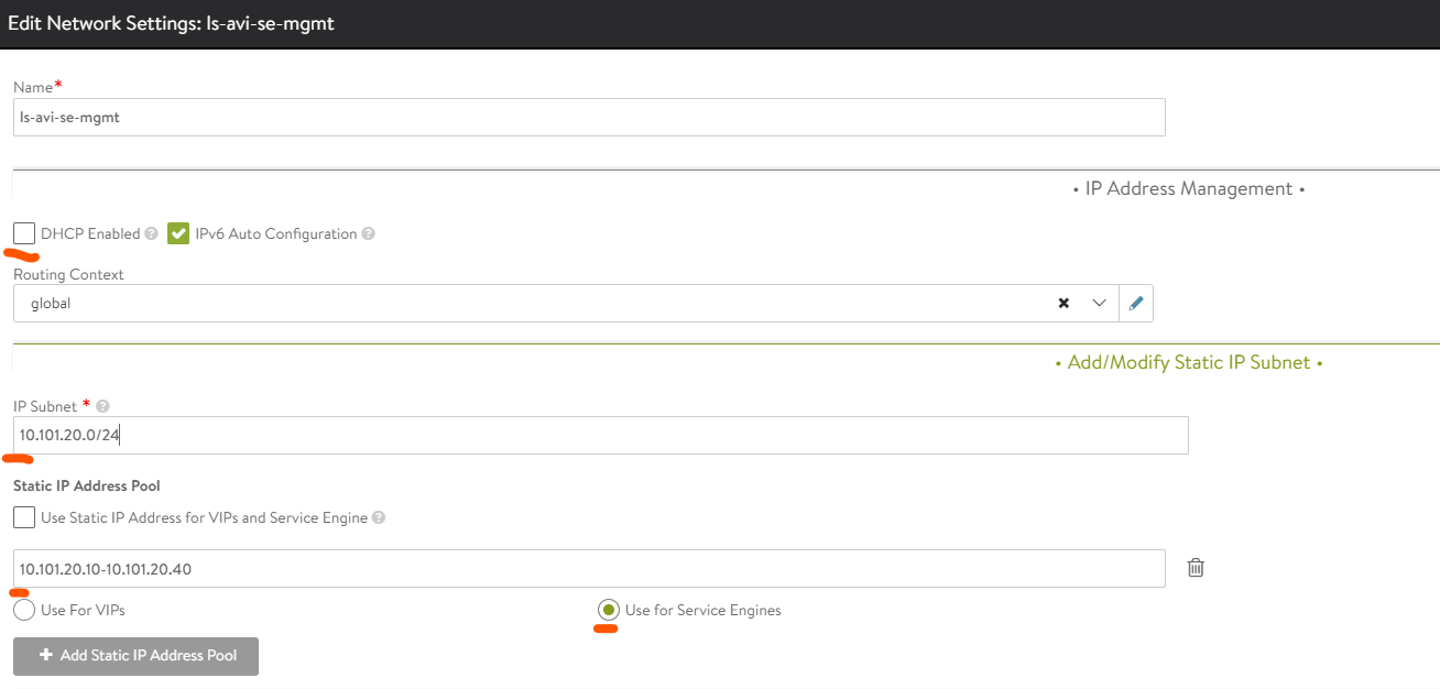
Deselect DHCP, we want to use Avi IPAM instead (and I dont have DHCP in these networks). Then fill in the CIDR (IP Subnet), deselect Use Static IP Address for VIPs and Service Engine add a range for the SE to be allow to get an IP from. Then select the Use for Service Engines. This will configure the IPAM pool to only be used for the dataplane for the SE’s in the management network. We dont want to have any VIPs here as it will only be used for the SE’s to talk to the Avi controller.
Then it is the ls-avi-generic-se-data network
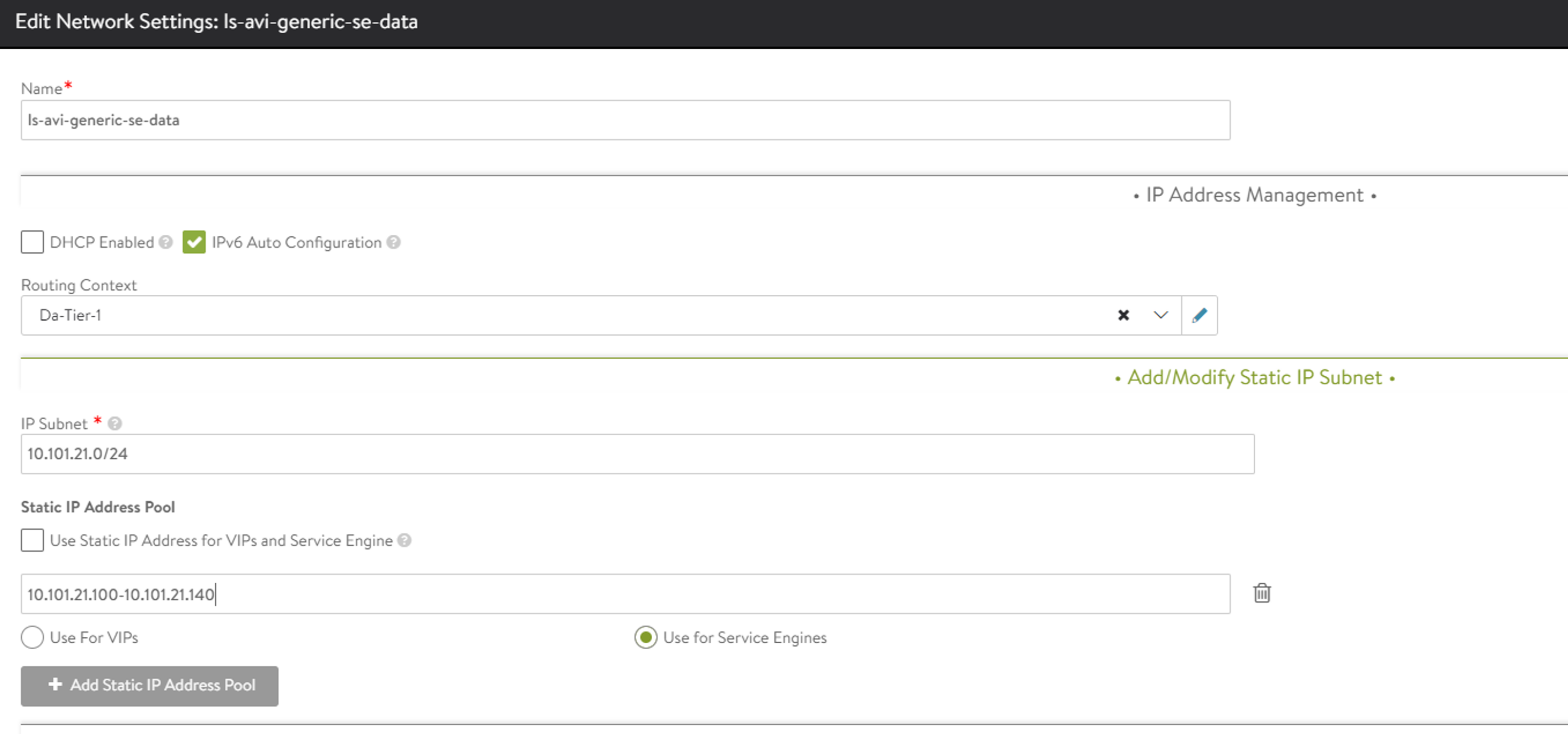
Same as above just a different subnet, using the same T1 router defined in NSX.
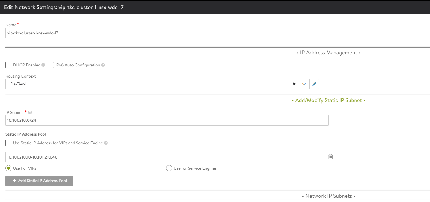
The two above networks will only be used as dataplane network. Meaning they will not be used for any Virtual Service VIP. We also need to define 1 or more VIP networks. Create one more network:
Here I specify a network which is only used for VS VIP
Avi IPAM/DNS template #
Now we need to inform our cloud which VIP networks we can use, that is done under Templates -> IPAM/DNS Profiles
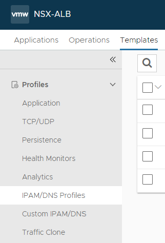
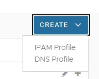
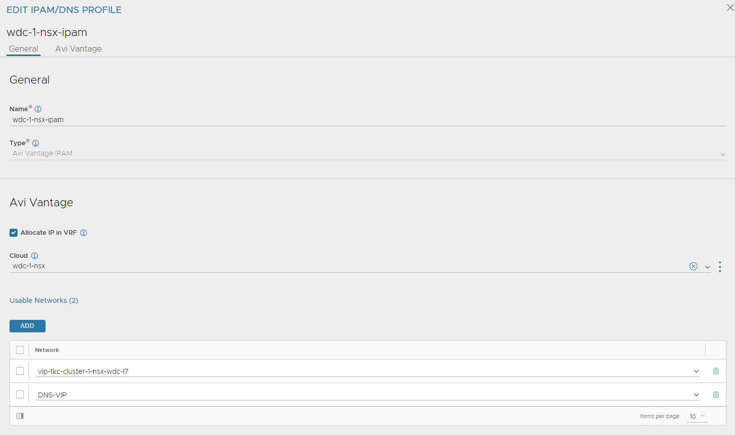
While we are here we create two profiles, one for DNS (for the DNS service) and IPAM profile for the VIP networks. Lets start with the IPAM profile. Click create right corner and select IPAM Profile:
Fill in name, select allocate IP in VRF and select your NSX cloud. Then click add and select your VIP networks defined above. Screenshot below also include a DNS-VIP network which I will use later. Click save.
Now click create again and select DNS profile:
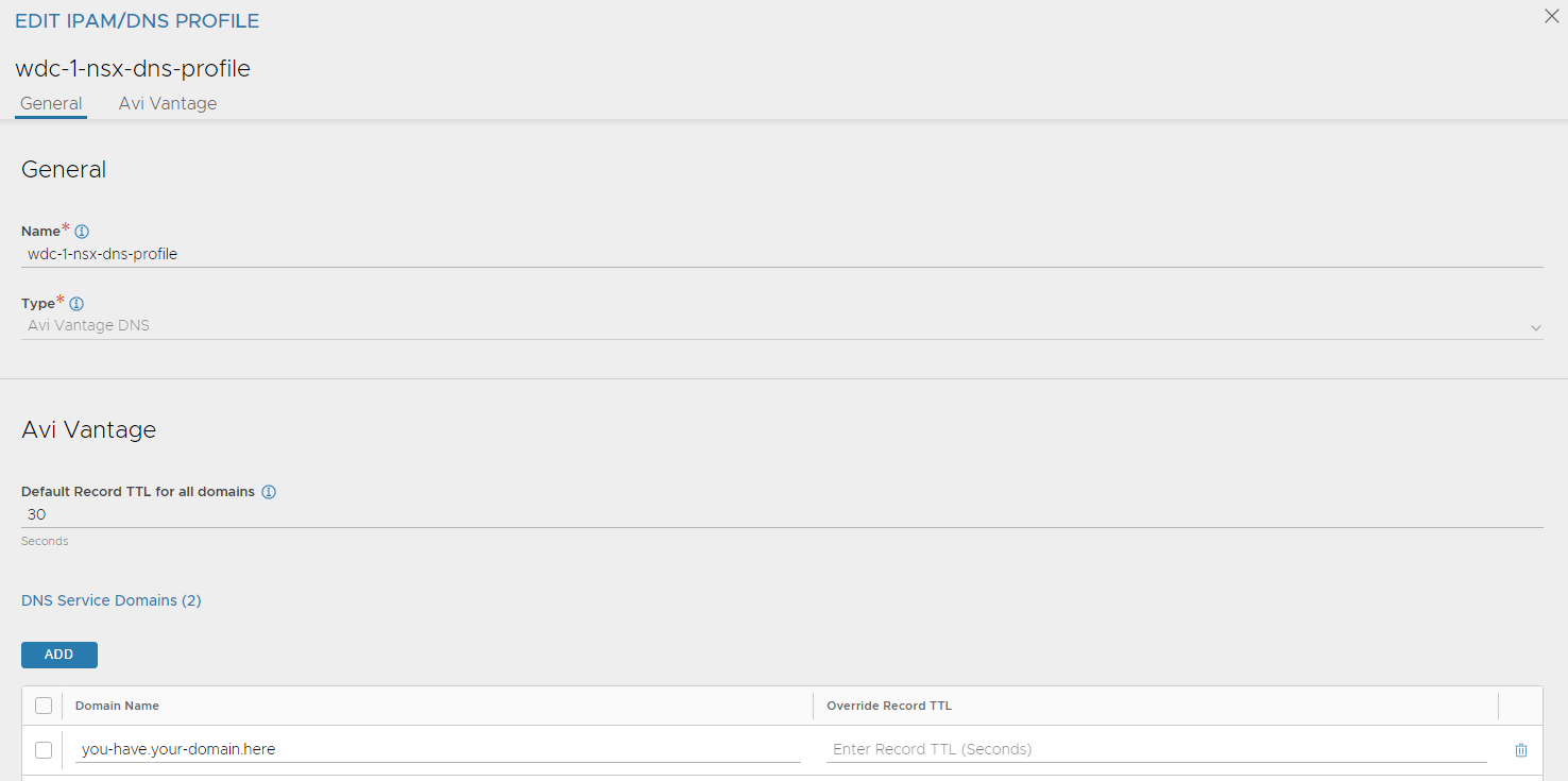
Give it a name and type in the domain name you want Avi to use.
Now go back to Infrastructure -> Clouds and edit your NSX cloud and add the newly added Profiles here:
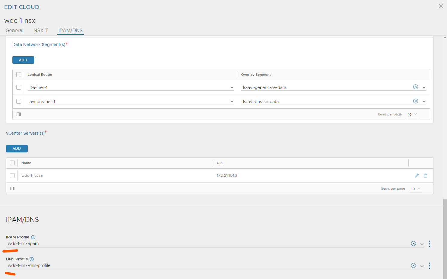
Save
Now Avi is prepared and configured to handle requests from AKO on L7 service Ingress. Next step will be to deploy configure and deploy AKO in our TKC cluster. But first some short words around Avi DNS service.
Avi DNS service #
Getting a virtual service with a VIP is easy with Avi, but often we need a DNS record on these VS’es. Avi has a built in DNS service which automatically register a DNS record for your services. The simplest way to make this work out of the box is to create a Forward Zone in your DNS server to the DNS Service IP for a specific subdomain or domain. Then Avi will handle the DNS requests for these specific domains. To make use of Avi DNS service we should dedicate a SE group for this service, and create a dedicated VIP network for it. As we should use a dedicated SE group for the DNS service it would be nice to also have a dedicated SE dataplane network for these SE’s. So follow the steps I have done above to create a SE network for the SE service SE’s and add this to your cloud. The VIP network also needs to be added to the IPAM Profile created earlier. A note on the additional SE network, this also requires a dedicated T1 router in the NSX environment. So in your NSX environment create an additional T1 router, create segment for the DNS SE datanetwork. This is how to enable the DNS service in Avi after you have prepared the networks, and IPAM profile:
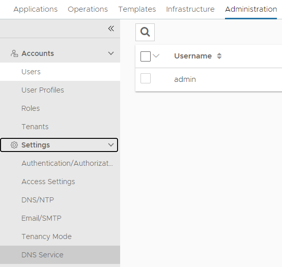
Head over to Administration -> Settings -> DNS Service:
Then create virtual service:
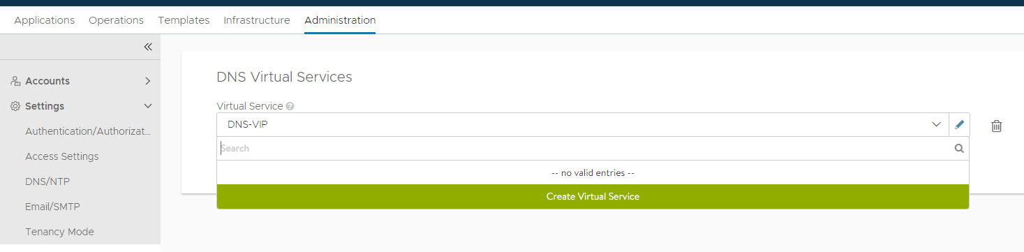
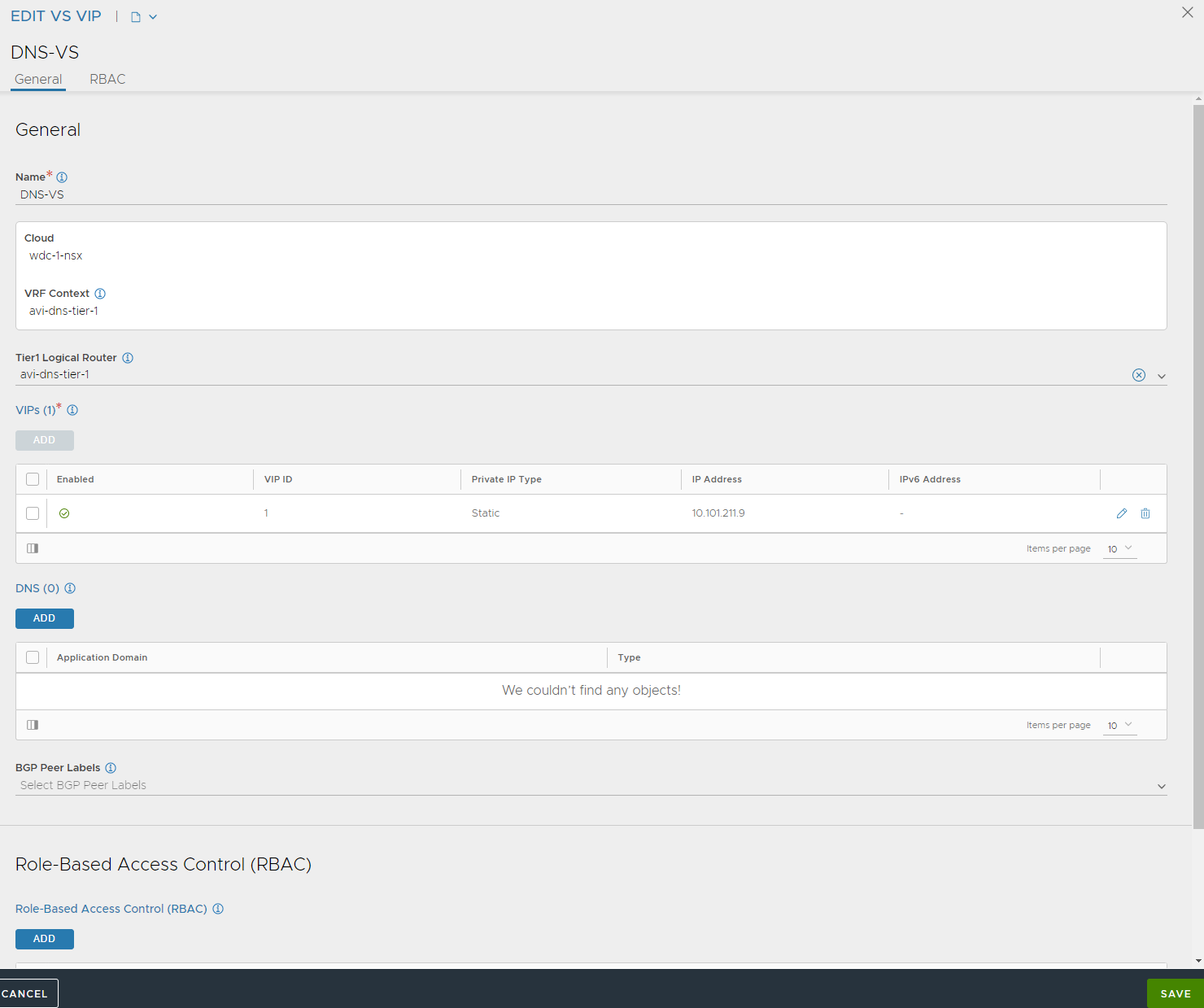
Select your cloud and configure the DNS service:
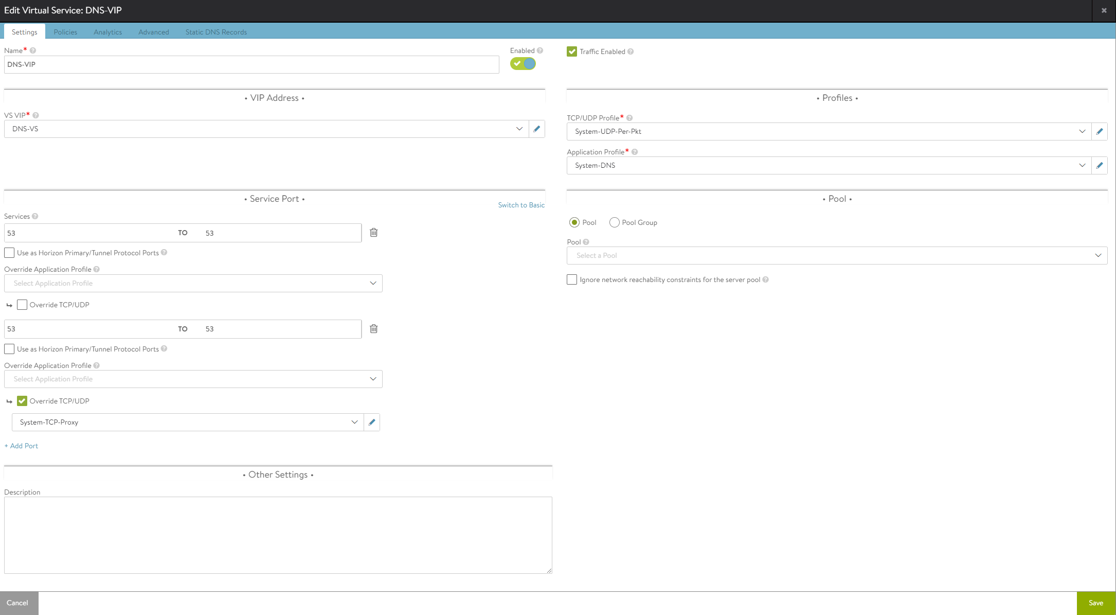
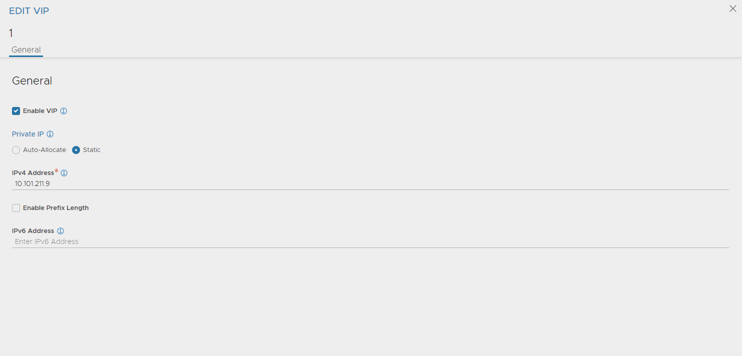
The VS VIP is configured with a static IP (outside of the DNS VIP IPAM range you have created)
Under advanced select the SE group:
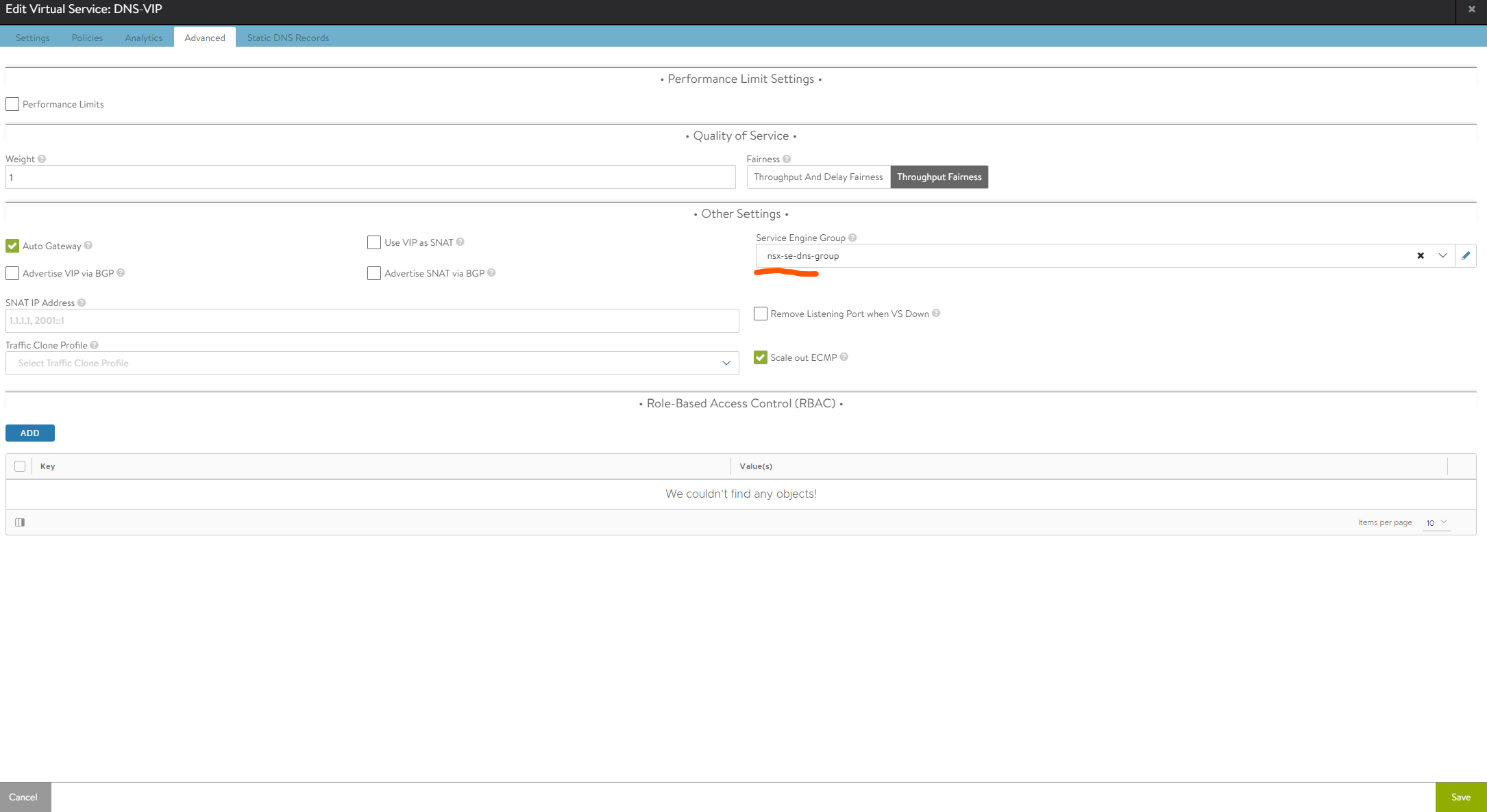
Save. Now the DNS VS is configured, go to templates and add a DNS profile:
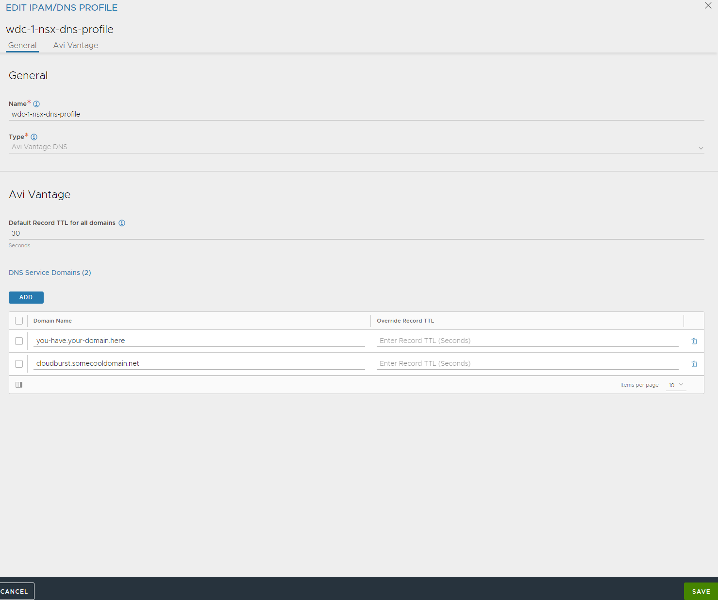
Give it a name, add your domain(s) here. Save
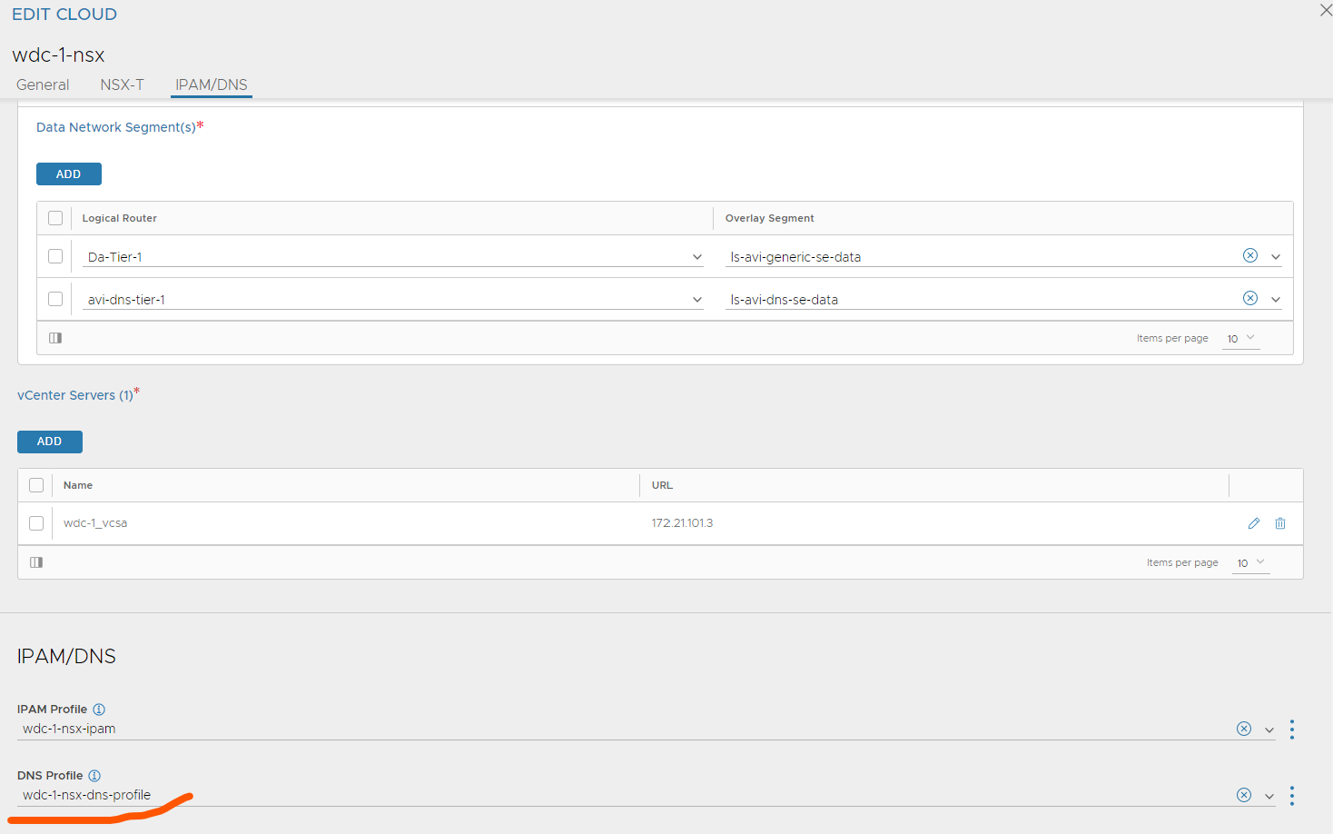
Head over to the cloud and add your DNS profile.
Now you just need to configure your backend DNS server to forward the requests for these domains to the Avi DNS VS IP. Using bind this can be done like this:
zone "you-have.your-domain.here" {
    type forward;
    forward only;
    forwarders { 10.101.211.9; };
};
AKO in TKC #
I have already deployed a TKC cluster, which is described here
Also make sure Antrea is configured with NodePortLocal as described also in the link above.
So for Avi to work as Ingress controller we need to deploy AKO (Avi Kubernetes Operator). I have also explained these steps here the only difference is how the value.yaml for AKO is configured. Below is how I have configured it to work in my NSX enabled environment with explanations:
# this file has been edited by me to easier reflect the changes I have done. So all default comments have been removed, and contains only my comments.
replicaCount: 1

image:
  repository: projects.registry.vmware.com/ako/ako
  pullPolicy: IfNotPresent


AKOSettings:
  primaryInstance: true
  enableEvents: 'true'
  logLevel: WARN
  fullSyncFrequency: '1800'
  apiServerPort: 8080
  deleteConfig: 'false'
  disableStaticRouteSync: 'false'
  clusterName: wdc-tkc-cluster-1-nsx   # Here we need to define a name for our specific TKC cluster. This must not be the exact names as the cluster itself, but why not, it MUST be unique across all your TKC clusters if you have multiple AKO enabled TKC/K8s clusters on same Avi controller
  cniPlugin: 'antrea' #This needs to be set to Antrea, the reason is that you would like to configure NodePortLocal.
  enableEVH: false
  layer7Only: true # This is very important to set to true as we already have an other AKO instance managing L4 for our k8s api endpoints. We will only configure this instance to use L7.

  namespaceSelector:
    labelKey: ''
    labelValue: ''
  servicesAPI: false
  vipPerNamespace: 'false'

NetworkSettings:
  nodeNetworkList:
  # nodeNetworkList:
    - networkName: "vnet-domain-c8:dd5825a9-8f62-4823-9347-a9723b6800d5-ns-wdc-1-tkc-cluste-62397-0" # this is the NSX segment created for your specific TKC cluster workers running in. In my case the defined portgroup name above. You can see this in vCenter
      cidrs:
      - 10.101.112.32/27 # this is the CIDR for your current TKC cluster (make sure you are using right CIDR, seen from NSX)
  enableRHI: false
  nsxtT1LR: 'Da-Tier-1' #The T1 router in NSX you have defined for the avi-se-dataplane network
  bgpPeerLabels: []
  # bgpPeerLabels:
  #   - peer1
  #   - peer2
  vipNetworkList:
    - networkName: "vip-tkc-cluster-1-nsx-wdc-l7" # This can be the same VIP network you have configured in previously for api endpint or it can be a completely new one. I am going the easy route using the same. It can be shared across multiple cluster (is using NodePortLocal), or can be specific for each tkc cluster.
      cidr: 10.101.210.0/24

L7Settings:
  defaultIngController: 'true' # Specify if this is the only Ingress controller you have or default if using several others.
  noPGForSNI: false
  serviceType: NodePortLocal # Here we select nodeportlocal - verify that Antrea is configured to use NodePortLocal
  shardVSSize: SMALL   # I am setting this to small so I can run more services using same IP.
  passthroughShardSize: SMALL
  enableMCI: 'false'

L4Settings:
  defaultDomain: ''
  autoFQDN: default


ControllerSettings:
  serviceEngineGroupName: nsx-se-generic-group   # If you dont decide to use the same VIP as k8s api endpoint you could decide to create an additional ServiceEngineGroup for your L7 services (IP separation etc).
  controllerVersion: '22.1.1' # AKO version 1.8.2 supports Avi 22.1.2
  cloudName: wdc-1-nsx   # The configured cloud name on the Avi controller.
  controllerHost: '172.21.101.50' # IP address or Hostname of Avi Controller
  tenantName: admin

nodePortSelector:
  key: ''
  value: ''

resources:
  limits:
    cpu: 350m
    memory: 400Mi
  requests:
    cpu: 200m
    memory: 300Mi

podSecurityContext: {}

rbac:
  pspEnable: false


avicredentials:
  username: 'admin' # username for the Avi controller
  password: 'password' # password for the Avi controller
  authtoken:
  certificateAuthorityData:


persistentVolumeClaim: ''
mountPath: /log
logFile: avi.log
Install AKO with this command:
helm install ako/ako --generate-name --version 1.8.2 -f values.yaml --namespace=avi-system
Check the logs of the AKO pod if it encountered some issues or not by issuing the command:
kubectl logs -n avi-system ako-o
If there is no errors there its time to deploy a couple of test applications and the Ingress itself. This is already described here
Thats it. Now L7 is enabled on your TKC cluster with Avi as Ingress controller. There is much that can be configured with AKO CRDs. I will try to update my post here to go through the different possibilites. In the meantime much information is described here
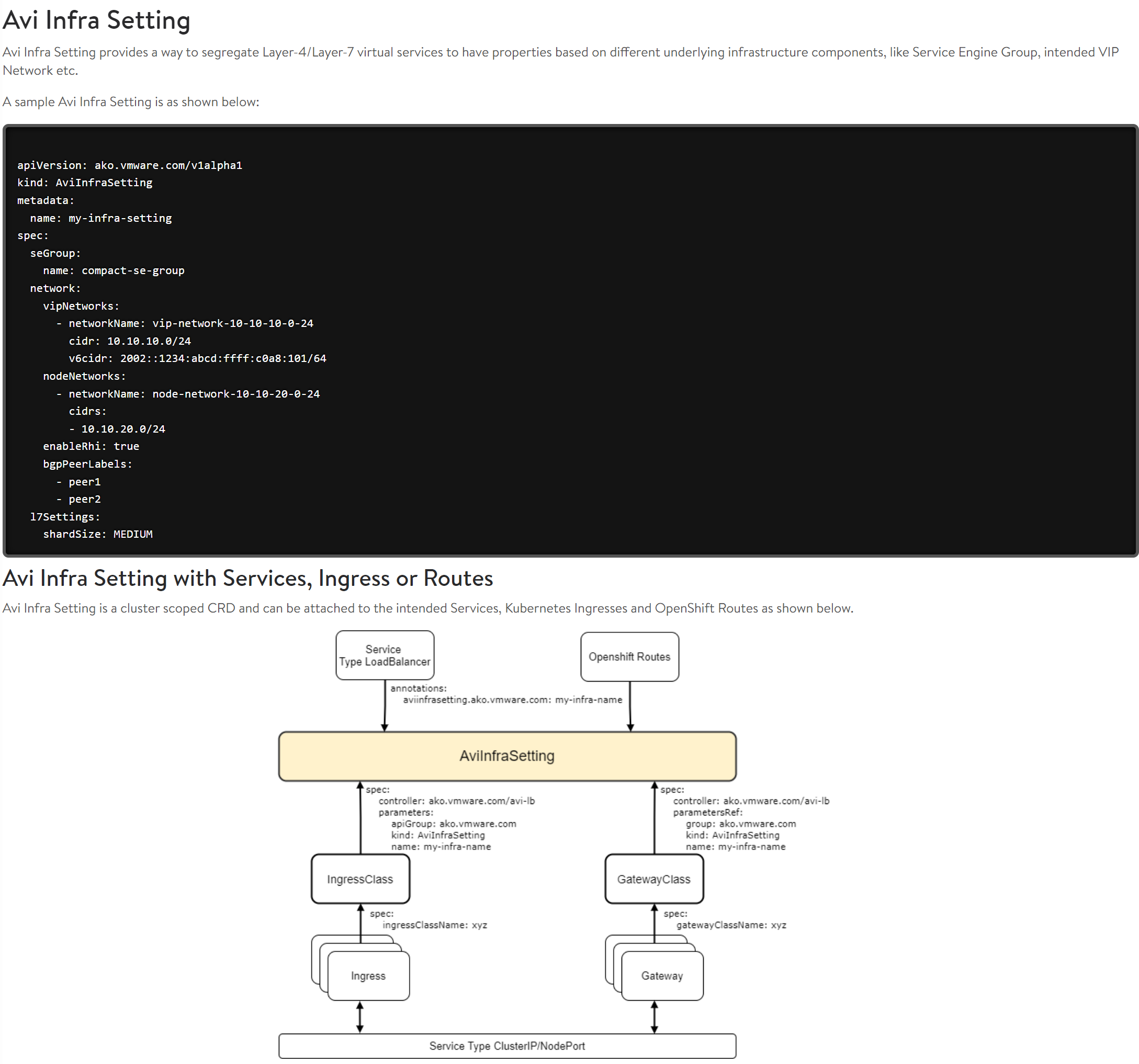
AviInfraSetting #
If you need to have separate VIPs/different subnets for certain applications we can use AviInfraSetting to override the “default” settings configured in our values.yaml above. This is a nice feature to override some settings very easy. There is also the option to run several AKO instances pr TKC/k8s cluster like described here which I will go through another time. But now quickly AviInfraSetting
Lets say I want to enable BPG on certain services or adjust my Ingress to be exposed on a different VIP network.
Create a yaml definition for AviInfraSetting:
apiVersion: ako.vmware.com/v1alpha1
kind: AviInfraSetting
metadata:
name: enable-bgp-fruit
spec:
seGroup:
name: Default-Group
network:
vipNetworks:
- networkName: vds-tkc-frontend-l7-vlan-1028
cidr: 10.102.8.0/24
nodeNetworks:
- networkName: vds-tkc-workload-vlan-1026
cidrs:
- 10.102.6.0/24
enableRhi: true
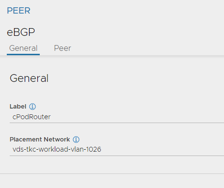
bgpPeerLabels:
- cPodRouter
In the example above I define the VIP network (here I can override the default confgured from value.yaml), the nodNetwork. Enable RHI, and define a label to be used for BGP (label is from BGP settings here):
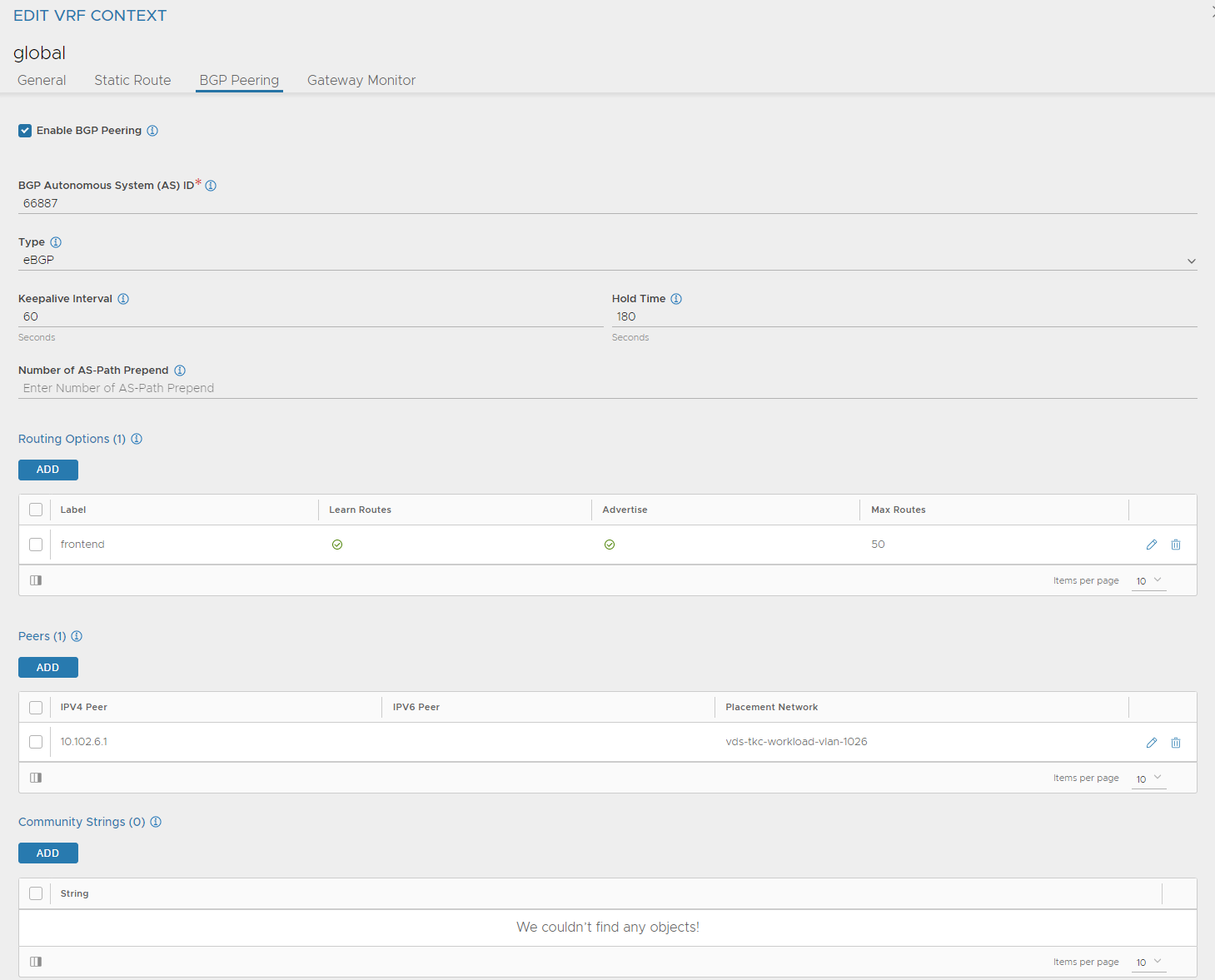
Peer:
Apply the above yaml. To use it, create an additional IngressClass like this:
apiVersion: networking.k8s.io/v1
kind: IngressClass
metadata:
  name: avi-lb-bgp #name the IngressClass
spec:
  controller: ako.vmware.com/avi-lb #default ingressclass from ako
  parameters:
    apiGroup: ako.vmware.com
    kind: AviInfraSetting #refer to the AviInfraSetting
    name: enable-bgp-fruit #the name of your AviInfraSetting applied
Apply it, then when you apply your Ingress or update it refer to this ingressClass like this:
apiVersion: networking.k8s.io/v1
kind: Ingress
metadata:
  name: ingress-example
  namespace: fruit

spec:
  ingressClassName: avi-lb-bgp #Here you choose your specific IngressClass
  rules:
    - host: fruit-tkgs.you-have.your-domain.here
      http:
        paths:
        - path: /apple
          pathType: Prefix
          backend:
            service:
              name: apple-service
              port:
                number: 5678
        - path: /banana
          pathType: Prefix
          backend:
            service:
              name: banana-service
              port:
                number: 5678